


Series 1780 Dynamometer User Manual V1.1
Document ID: Q2D4F5
Publish date: 2020-03-06
❏
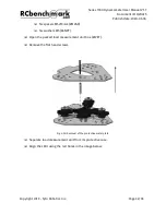
Screw the female part of the nine M5 standoffs with the M5 screws and tighten them
well, as shown in Fig. 4.29:
Fig. 4.29: Connection of the screw, washer and the standoff to the load measurement unit
❏
Take out all the assembly of the motor mount, with the motor and optical RPM probe.
❏
Take out the locknuts (#YTEX) from the load measurement unit and motor mount
fasteners bag (#VQMD).
❏
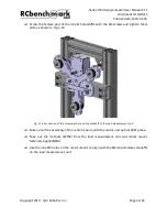
Use the nine M5 holes on the motor mount to align with the M5 male-female standoffs
on the load measurement unit.
Copyright 2019 - Tyto Robotics Inc.
Page 44/65


