


Series 1780 Dynamometer User Manual V1.1
Document ID: Q2D4F5
Publish date: 2020-03-06
❏
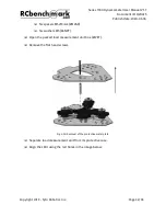
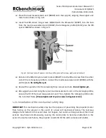
Adjust the radial distance between the sensor head of the probe and the rotor edge,
using the slots on the circuit. Make sure the gap between the optical sensor and the
motor shown as e in Fig 4.27, to respect the specifications.
Fig. 4.27: Gap control between the probe and the motor
❏
The recommended “e” gap distance between the motor and the probe is:
●
2~4mm for Optical RPM probe V2.0
●
<10mm for Optical RPM probe V2.1
❏
Once the probe reaches the appropriate distance from the motor, fully tighten all the
screws with an allen key.
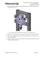
IMPORTANT!
The distance between the motor and the head of the optical sensor is important. It must be
kept under certain distance for the optical sensor to work effectively.
The optical probe is very close to spinning parts. Check fasteners are tight before every test
in order to prevent the optical probe slipping and colliding with the rotor.
Copyright 2019 - Tyto Robotics Inc.
Page 41/65


