

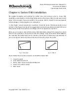


Series 1780 Dynamometer User Manual V1.1
Document ID: Q2D4F5
Publish date: 2020-03-06
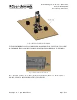
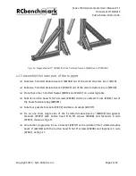
Fig. 4.10: Diagonal beam 12” (#JTKA) fix to the T-slotted frame 4’ (#HJXQ) and 10” (#FUBH)
4.1.3 Assembly the lower part of the support
❏
Take two T-slotted double beam 4” (#WHXZ) out of the stand structure box 1 (#TJLD).
❏
Take two T-slotted double beam 3’ (#LNKY) out of the stand structure box 2 (#YXHR).
❏
Place these four T-slotted frames (#WHXZ and #LNKY) on a working table.
❏
Take ten button head 5/16-18 screws (#KEDB) and ten end-feed T-nuts (#YREC) out of
the beam fasteners bag (#WVKM).
❏
Take four gussets brackets (#YKPV) and two L-brackets (#KPHT).
❏
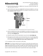
Fix on one short single side of the T-slotted double beam 4” (#WHXZ) two gussets
brackets (#YKPV) with button head 5/16-18” screws (#KEDB) and fasteners T-nuts
(#YREC), shown as Fig 4.11.
❏
On another single side, fix an L-bracket (#KPHT) at the middle of the T-slotted double
beam 4” (#WHXZ) with the button head 5/16-18” screws (#KEDB) and fasteners T-nuts
(#YREC), as Fig 4.11:
Copyright 2019 - Tyto Robotics Inc.
Page 23/65


