


Series 1780 Dynamometer User Manual V1.1
Document ID: Q2D4F5
Publish date: 2020-03-06
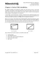
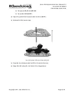
Fig 4.15: Insert screws (#STHN) through washers (#BLGN) and spacers (#AEUG)
❏
Repeat the last steps for the second rectangular tube profile (#XLGF).
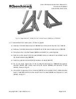
❏
Insert and slide in this assembly on the T-slotted frame 4’ (#HJXQ) with allen key ¼“
(#QYHR), do not fully tighten the 5/16-18” socket head screws until you place the load
measurement unit onto the support:
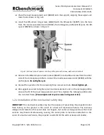
Fig 4.16: Rectangle profile (#XLGF) fix to T-slotted frame 4’ (#HJXQ)
❏
Double-check if other fasteners are mounted on the support, and if they were well
tightened.
❏
Under some circumstances, the load measurement unit may need extra adjustment to
be mounted on the support. If necessary, slightly untighten the screws from the 7” and
the rectangular tube to increase clearance.
❏
Place the finalized support on the ground.
Copyright 2019 - Tyto Robotics Inc.
Page 27/65


