


Series 1780 Dynamometer User Manual V1.1
Document ID: Q2D4F5
Publish date: 2020-03-06
❏
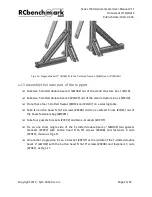
Place the load measurement unit (#EXBE) onto the support, aligning these upper and
lower holes shown in Fig. 4.23.
❏
Insert four M5-40mm long screws (#QACR) with the M5 washer (#4N9T), into the hole
from the load measurement unit (#EXBE), the rectangular profile (#XLGF) plus the M5
spacer (#MVAK) as shown in Fig 4.23:
Fig 4.23: Sectional plan of spacers into the profile plate with screws, washers and locknuts
❏
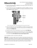
Rotate in the M5x0.8 nylon-insert locknut (#BAKT) into the M5-40 screw from the other
side of the rectangular profile to connect the load measurement unit (#EXBE) with the
profile plate. Do not tighten yet.
❏
Repeat the operation for the remaining three screws and nuts. Do not tighten yet.
❏
We suggest you start to tighten your load measurement unit on the rectangle profile,
ensure the fit of the load measurement unit. Then, tighten the rectangle profile onto
the T-slotted frame. [Please tighten all of your screws in diagonal order].
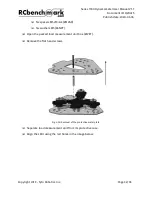
4.2.4 Installation of the mechanical safety stop
IMPORTANT! This mechanical safety stop has the purpose of preventing the propeller/motor
from falling on the ground in the event of a load cell mechanical failure. The tool was
designed and tested so this event does not happen, but under a strong overload, the 3 load
sensors may break simultaneously, causing the motor plate to become unattached. In the
event of a load sensor failure, the propeller could still hit the vertical beam and shatter.
Copyright 2019 - Tyto Robotics Inc.
Page 34/65


