EN
7
Various methods in connecting with TV
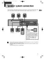
Connecting with TV
■
During initial setup, the RF output channel for video is set to CH 3. This setting can be changed from the
“Channel SET” screen in VCR operation (refer to page 13).
■
To see the picture from this unit, set your TV to CH3 once the RF cable is connected.
Audio connection
Connect the Audio cables (red and white)from the Audio/Video (composite) cable to the Audio Jack
on the back of the DVD-Video player and the TV. Match the colour between the cable and the jacks
when making the connections. Connect the left (white) and right (red) audio cables to the
AUDIO
OUT
L(white) and R (red) jack on the DVD-Video player and the
AUDIO IN
jacks on the TV.
AUDIO
VIDEO
S-VIDEO
ANT INPUT
S-VIDEO INPUT
A/V INPUT
COMPONENT INPUT
CAUTION
CAUTION: TO REDUCE THE RISK OF ELECTRIC SHOCK.
DO NOT REMOVE COVER (OR BACK).
NO USER SERVICEABLE PARTS INSIDE.
REFER SERVICING TO QUALIFIED SERVICE PRESONNEL.
RISK OF ELECTRIC SHOCK
DO NOT OPEN
20
18
16
14
12
10
8
6
4
3
21
19
17
15
13
11
9
7
5
3
1
FRONT-R
FRONT-L
REAR-L
WOOFER
REAR-R
CENTER
SPEAKER
COMPONENT OUT
IN 1
IN 2
OUT
S-VIDEO OUT
WOOFER OUT
AUDIO
ANT.IN
AM
FM
RF.OUT
R
L
VIDEO
Pr
Pb
Y
IMPEDANCE USE 6
Ω
(WOOFER USE 6
Ω
)
<Outside Antenna or
Wall Antenna Outlet>
RF Cable
Connection
Basic Audio/Video
Connection
<Rear Panel of TV>
<Rear Panel of unit>
Optional (DVD only)
Optional (DVD only)
RTD300 EN 7/25/03 2:36 PM Page 11


