background image

hsb

2


PLUS Series

Fishfinders

Owner’s 
Handbook

Document number: 81195_2
Date: August 2002

Summary of Contents for hsb2 PLUS

Page 1: ...hsb2 PLUS Series Fishfinders Owner s Handbook Document number 81195_2 Date August 2002...

Page 2: ......

Page 3: ...e procedures and tools only available to qualified service technicians there are no user serviceable parts or adjustments The operator should never remove the display unit cover or attempt to service...

Page 4: ...s for Fishfinders Owner s Handbook This handbook contains very important information on the installation and operationofyournewfishfinder Inordertoobtainthebestresultsinoperation and performance pleas...

Page 5: ...aymarine com Warranty To register your hsb2 Plus Series display unit ownership please take a few minutes to fill out the warranty registration card found at the end of this handbook It is very importa...

Page 6: ...ited hsb2 is a trademark of Raymarine Limited Pathfinder Plus is a trademark of Raymarine Limited ThisproductcontainstechnologyprovidedunderlicensebyAcornGroupplc The copyright of this intellectual pr...

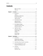
Page 7: ...splay 1 12 Chartplotter Display Options 1 13 Chartplotter Functions 1 15 1 4 Operating Controls 1 16 Trackpad and Cursor 1 17 Dedicated Keys 1 19 Soft Keys 1 19 Pop Up Menus 1 20 Database Lists 1 21 C...

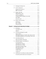
Page 8: ...1 3 1 Introduction 3 1 Conventions Used 3 1 Simulator 3 1 3 2 Switching the Display On and Off 3 2 Simulator Mode 3 5 Changing the Lighting Contrast Monochrome LCD 3 6 Changing the Brightness Color S...

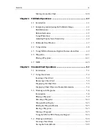
Page 9: ...ing a Waypoint 4 11 4 7 MOB 4 13 Chapter 5 Standard Chart Operations 5 1 5 1 Introduction 5 1 5 2 Using Chart Cards 5 2 Inserting a Chart Card 5 2 Removing a Chart Card 5 3 Displaying the Chart Data 5...

Page 10: ...Stop Goto 5 34 5 6 Transferring Waypoints and Routes 5 35 5 7 Using Tracks 5 39 Setting Up a Track 5 40 Clearing the Current Track 5 40 Managing Tracks 5 40 SmartRoute 5 42 5 8 Typical Chart Scenarios...

Page 11: ...Up 7 8 Menu Timeout Period 7 8 Units 7 8 Variation Source 7 8 Bridge NMEA Heading 7 9 NMEA Out Set Up 7 9 Cursor Echo Systems with Radar Display 7 11 Date and Time Settings 7 11 GPS SOG COG Filter 7 1...

Page 12: ...ning Instructions 8 1 EMC Servicing and Safety Guidelines 8 2 8 2 Resetting the System 8 3 8 3 Problem Solving 8 4 How to Contact Raymarine 8 5 Worldwide Support 8 7 Appendix A Specifications A 1 hsb2...

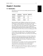
Page 13: ...otandRaystarWideAreaAugmentationSystem WAAS GPS products Connecting an hsb2 Series Plus Fishfinder to an hsb2 Series Pathfinder Plus Radar and to an hsb2 Series Plus Chartplotter enables fishfinder ra...

Page 14: ...ns Chapter 3 also provides operating guidelines for typical chartplotter scenarios these guidelines introduce you to many of the chartplotter functions Chapters 4 provides detailed operating informati...

Page 15: ...er A unit capableof displaying data suchas radar from the High Speed Bus Fishfinder Display Unit providingFishfinder Master and Radar Repeater functionality TheL755RC L760RC and L1250RC Plus displays...

Page 16: ...lity changes Two slots for the C MAP NT or NT chart cards Raychart models only The display and keys can be illuminated for night time use Transducer The hsb2 Plus Series Fishfinders require a transduc...

Page 17: ...or CRT displays to provide an integrated system Earlier HSB non Plus Display units can be upgraded to provide hsb2 compatibility See Connecting hsb2 Plus Series Displays on page 2 20 for details Note...

Page 18: ...hfinder chart and data log are available you select the operating mode using the DISPLAY key as described in Chapter 3 YoucanalsosetWindowsOntosplitthedisplayintotwohalf screenwindows toshowsupplement...

Page 19: ...a relating to the target waypoint Nav Data Chart mode This shows sixteen data boxes providing navi gational data in the units specified in your set up Note that up to 6 of these data boxes are also av...

Page 20: ...The fishfinder screen includes a status bar that displays transducer frequency and indicates which auto settings are enabled Gain Color Gain Range Zoom and Frequency and alarm status fish and shallow...

Page 21: ...eously or auto frequency The default setting is auto frequency which determines the optimum frequency of operation based on the current depth Bottom Lock changes the operating mode to re set the botto...

Page 22: ...Bottom Lock or A Scope can be displayed with the dual frequency graph All of these options are available when the fishfinder is displayed in a half screen window Fishfinder Functions The hsb2 Plus Ser...

Page 23: ...0kHz SPLIT 0 100 ft ZOOM FREQUENCY 25 25 35 25 6 35 35 25 35 BTM LOCK A SCOPE AUTO G Z 0 100 7 9 52 3 200kHz 50kHz 200kHz 50kHz SPLIT 0 100 ft ZOOM FREQUENCY BTM LOCK A SCOPE AUTO G Z 200kHz 5 10 15 2...

Page 24: ...COG data is available the vessel is shown as a circle The chartplotter screen includes a status bar that displays chart scale with either cursor position range and bearing or when the cursor is homed...

Page 25: ...off You can also obtain autopilot status and locked heading information Display options are provided in System Set Up and Chart Set Up as described in Chapter 7 Chart set up options allow you to custo...

Page 26: ...ing light sectors marine features Note The factory default for the CUSTOM settings is ON Icons are displayed in detail depth shading limit is 10 m and depth contour display is 0 100 m A complete list...

Page 27: ...for the Nearest Port Place Move Erase and Edit a Waypoint Goto Waypoint or Cursor Create Save Name Edit and Follow a Route Review Route and Waypoint Lists Display vessel s track Save and Name the Tra...

Page 28: ...displayed on screen which enable you to edit items Note Thecursoristhecross hairsymbol visibleonthedisplay Youmove the cursor using the trackpad and use it to select a position or item on the chart Th...

Page 29: ...a position on the screen Select an item for example chart object on the chartplotter Pan the chart display Moving the Cursor You can press on any of the four sections of the trackpad to move the curso...

Page 30: ...display a text label appears to identify the feature as follows Some items on the fishfinder chartplotter screen such as the cursor have information associated with them Most information is displayed...

Page 31: ...ey action If the key press is not valid for the current screen or mode three rapid beeps sound to indicate that no response is available If required you can turn the key beeps off as part of your set...

Page 32: ...part of your set up procedure see Chapter 7 Pop Up Menus Pop up menus usually provide set up options When a pop up menu is on screen a set of associated soft keys is also displayed as shown in Figure...

Page 33: ...database list is on screen a set of associated soft keys is also displayed you use the trackpad to select an item from the list then use the appropriate soft key to edit the item For example you caner...

Page 34: ...1 22 hsb2 Plus Series Fishfinders Database Lists...

Page 35: ...ystems such as that in Figure 2 1 below or integrated systems such as that in Figure 2 2 are explained see Section 2 7 Details for mountingthehsb2 PlusSeriesLCDDisplayandconnectingtheequipmentare incl...

Page 36: ...o other equipment as described in Section 2 7Integrated Systems on page 2 18 taking particular care to ensure the correct polarity of the SeaTalk supply Section 2 7 describes the hsb2 SeaTalk and NMEA...

Page 37: ...ribe the conditions for optimum EMC performance butitisrecognizedthatitmaynotbepossibletomeetallofthese conditions in all situations To ensure the best possible conditions for EMC performance within t...

Page 38: ...ion Suppression Ferrites The following illustration shows typical cable suppression ferrites used with Raymarine equipment Always use the ferrites supplied by Raymarine Figure 2 3 Typical Suppression...

Page 39: ...splay Sun cover 10 4 LCD Display Sun cover D331 E55031 L755RC L760 L760RC L1250 L1250RC Handbook Fishfinder Chart Quick Reference Card Fishfinder Quick Reference Card Chart 81195 86066 86067 All All L...

Page 40: ...0 ft 10 m 60 ft 20m hsb2 In Line Terminator hsb2 Splitter Cable NMEA OUT cable assy 4 ft 11 in 1 5m R55001 R55002 R55003 R55004 E55010 R58117 E55040 R55005 All All All All All All All All Transducer a...

Page 41: ...el connectors avoiding tight bends in the cable Interference The selected location should be far enough away from devices that may cause interference such as motors generators and radio transmitter re...

Page 42: ...MARKS ALARMS RANGE ENTER CLEAR MENU POWER Weight 8 1 lbs 3 7 Kg Compass Safe Distance 39 in 1 m 10 51 in 267 mm 0 95 in 24 3 mm 6 89 in 175 mm 0 4 in 10 mm 7 3 in 185 mm 8 1 in 205 2 mm 8 8 in 223 6...

Page 43: ...ENTER CLEAR MENU POWER Weight 7 5 lbs 3 415 Kg Compass Safe Distance 39 in 1 m 10 54 in 267 7 mm 0 95 in 24 mm 6 89 in 175 mm 0 95 in 24 mm 0 4 in 9 5 mm 7 3 in 185 mm 8 in 204 mm 0 4 in 9 5 mm 8 76...

Page 44: ...ns L1250 and L1250RC Plus D5066 3 11 5 in 292 mm 3 82 in 97 mm 6 38 in 162 mm cable clearance Compass Safe Distance 39 in 1 m 12 9 in 328 mm 9 7 in 246 mm 0 87 in 22 1 mm 7 88 in 200 mm 1 7 in 43 mm 1...

Page 45: ...nit and 7 wires at the otherendforconnectingthepowersupplyandoptionalNMEA inputs see Integrated Systems on page 2 18 Transducer cable supplied with the transducer This 30 ft 10 m cable has a connector...

Page 46: ...tional flush mounting kit see Section 2 2 Mounting Bracket Thedisplayunitcanbemountedonadash chart table bulkhead ordeckhead Figure 2 7 LCD Display Mounting 1 Loosen the knobs and remove the mounting...

Page 47: ...Using the supplied template trace out the display unit opening 4 Drill a in 12 7 mm pilot hole in each corner of the cut out area 5 Using a suitable saw cut along the inside edge of the cut out line...

Page 48: ...be made at either the output of the battery isolator switch or at a DC power distribution panel Raymarine recommends that power is fed directly to the display via its own dedicated cable system and MU...

Page 49: ...isplayunitconnectorsusedwheninstalling a single hsb2 Plus Series LCD Display The remaining connector details are provided in Section 2 7 Transducer Connection master displays The transducer cable conn...

Page 50: ...njunction with a speed temperature transducer attach the 7 pin female connector on theY cable to the display then attach the transducer cable to the 7 pin male connector on the Y cable Note If your sy...

Page 51: ...re connected for correct polarity Switch off the display unit before you remove the power cord The RED wire must be connected to the feed from the positive battery terminal and the BLACK wire to the f...

Page 52: ...n the display Data can be transmitted via SeaTalk and NMEA to enhance other equip ment Some incoming data can be converted across the communication link and re transmitted Power for External Equipment...

Page 53: ...to provide fishfinder chart and radar functionality on all threedisplays Youcandisplaysomecombinations suchasfishfinder chartor radar chart in half screen windows Note FishfinderSTCcannotbeadjustedona...

Page 54: ...units or one software only upgraded with one true Plus or Plus upgraded display Connecting hsb2 Plus Series Displays Figure 2 11 illustrateshow tointer connectvarioushsb2 PlusSeriesDisplays When conn...

Page 55: ...internally Like the old HSB system this configuration only supports two displays two software only upgraded units or one software only upgraded with one true Plus or Plus upgraded display An In Out c...

Page 56: ...is no other depth data on SeaTalk Fishfinder depth is transmitted If speed and temperature data are available on SeaTalk the Fish finder uses thisdata if thisdataisnot on SeaTalk from otherinstruments...

Page 57: ...nd SeaTalk Instruments 12 24V Supply 12 24V Supply 12 24V Supply 12 24V Supply HSB HSB 12 24V Supply 12 24V Supply SeaTalk SeaTalk SeaTalk SeaTalk SeaTalk GPS hsb2 Series Radar hsb2 Series Chartplotte...

Page 58: ...into the network SeaTalk is a precise high speed bi directional protocol which is flexible enough to adapt to any number of instruments without a central processor SeaTalk equipment can also communic...

Page 59: ...as a SeaTalk output To connect the display unit to the SeaTalk bus connect a standard SeaTalk cable between the SeaTalk connector on the rear of the display and a SeaTalk instrument or the SeaTalk bus...

Page 60: ...position and navigation data to a radar NMEA Input Connection The two NMEA Power input connectors are normally used for non SeaTalk Compass heading data or GPS It can also be used for additional navi...

Page 61: ...t to 12 V power if required Input connections to connect SeaTalk cable from external equipment Spare connections for another instrument CAUTION Ensure correct polarity of the 12 V supply before applyi...

Page 62: ...ions links as follows NMEA In to NMEA Out and SeaTalk SeaTalk to NMEA Out Thisenablesdatareceivedbythedisplaytobepassedtootherinstruments For example if youhaveamaster andarepeaterdisplay you onlyneed...

Page 63: ...the center of the chart display 3 Insert a chart cartridge for the area of your vessel Use the RANGE key to zoom in to check that the chart data is being dis played Received Data If either SeaTalk or...

Page 64: ...2 30 hsb2 Plus Series Fishfinders Transmitted Data...

Page 65: ...s menu names and options are shown in normal capitals for example SCREEN Operating procedures which may consist of a single key press or a sequence of numbered steps are indicated by a symbol in the m...

Page 66: ...ors as describedlater in this chapter Setting the Fishfinder as Master Repeater You need to set your display as a fishfinder master or repeater If the display is connected to a sonar transducer it is...

Page 67: ...er Display at Switch On To set the fishfinder display as a master or repeater 1 Press the MENU key then press the SONAR SET UP soft key The sonar set up pop up window is displayed 2 Use the trackpad t...

Page 68: ...avigation Rather yourRaychartshouldbeused onlyasabackuptoofficialgovernmentchartsandtraditionalmethodsof navigation Whenyouhavereadandunderstoodthecaution presstheCONTINUE softkey The chart is display...

Page 69: ...iew simulated image 1 Press MENU followed by either the SYSTEM SET UP soft key for simulated data or the SONAR SET UP soft key for a simulated fishfinder image The set up menu pop up is displayed 2 Us...

Page 70: ...ontrast levels 6 Press ENTER to return to the default screen with the new lighting and con trast levels retained or press CLEAR to discard the changes and return to the default screen If lights are le...

Page 71: ...t the screen brightness to 100 Press and hold the MULTI key for one second The brightness is increased to 100 The brightness level is retained when you switch off the display Note During night time us...

Page 72: ...d minimum Ifyoublankacolor thecorrespondingechoesaredisplayedinthebackground color You can remove up to six colors but you cannot remove the strongest color The color threshold you select is used on a...

Page 73: ...u may need to press ENTER or CLEAR several times to back track through the soft key hierarchy Note If you have set up your system so that the default soft keys are not dis played all the time press an...

Page 74: ...The default soft keys are displayed The selected mode is shown full screen in Fishfinder and Chart mode you can switch on half screen windows for additional display as described in the following sect...

Page 75: ...Fishfinder mode on all displays In Chartplotter mode on all displays 37 70 LIGHT CONTRAST WHT LINE OFF ON D4895 2 POWER AUTO LO HI 70 LIGHT WHT LINE OFF ON POWER AUTO LO HI COLOR SETTINGS D4896 2 70...

Page 76: ...screen image they are switched off until you return to full screen mode However you can use the SCREEN soft key in chart mode to switch the data boxes on they are displayed in the upper window Figure...

Page 77: ...n gray monochrome LCD or red color LCD on the CHRT SNR label and the cursor appears in that window Returning to the Full Screen Display To return to the full screen display you can turn windows off as...

Page 78: ...EQUENCY BTM LOCK A SCOPE AUTO G RZ 50kHz XTE 225 T 40 30 20 20 10 10 nm nm WPT BRG WPT RNG TTG 1 45nm 23 1nm 01h 13m STEER STARBOARD WAYPOINT 001 351 T SELECT WINDOWS WINDOWS OFF ON SPLIT HOR VER AUTO...

Page 79: ...le on your system You select which data is displayed in the boxes during system set up as described in Chapter 7 The default databoxpositionsarealongthebottom of thedisplay Eachboxcan bemoved to the r...

Page 80: ...is not related to the speed of the boat over the bottom You can also pause the display the depth indication continues to be updated To change the scrolling speed 1 Press MENU then press the SCROLL SP...

Page 81: ...finder switches to HI power regard less of what the digital depth is calculated to be If however you wish to manually adjust the power to suit current conditions you can select either LO or HI power T...

Page 82: ...om an L1250 Plus or L1250RC Plus via the High Speed Bus Table 3 1 Range and Shift Values Feet Fathoms Meters Range Shift Range Shift Range Shift 5 1 1 1 2 1 10 2 2 1 4 1 15 5 3 1 6 2 20 5 4 1 8 2 30 1...

Page 83: ...t is stronger than the return from the bottom In this a case it is possible the fishfinder may determine the clutter to be the seabed rather than the bottom itself You can use the RANGE setting to for...

Page 84: ...roduces a more detailed view The 200 kHz signal is good for finding fish near the bottom or close together It is better for use in shallow water Split Frequency The transducer can operate in both 50 k...

Page 85: ...rom the surface of the water Bottom Lock shows a water column of fixed height referenced from the bottom that appears flat It removes bottom detail to provide an image of objectsdirectlyabovethe botto...

Page 86: ...ay is split vertically with the bottom lock image in the left hand window and the scrolling bottom display in the right hand window In a split window display a vertical bar appears along the right han...

Page 87: ...e A Scope image 1 PresstheA SCOPEsoftkey Thedisplayissplitvertically withtheA Scope image in the right hand window and the scrolling bottom image in the left hand window 2 Press the A SCOPE MODE soft...

Page 88: ...plit vertically with the zoom image intheleft hand window and the scrolling bottom display in the right hand window In a split window display a vertical bar appears along the right hand edge of the sc...

Page 89: ...text ZOOM is displayed near the cursor 2 PressENTER ahorizontallineappears indicatingthecursor isactive Use the trackpad to select the new position 3 Press ENTER to reposition the zoom image or CLEAR...

Page 90: ...y includes grid lines of latitude and longitude which you can use to help determine position on the chart The grid lines can be switched on if required To turn the chart grid on or off 1 Press the SCR...

Page 91: ...t up menu as described in Section 7 3 To move any data box 1 UsethetrackpadtopositionthecursorovertheboxuntilthelettersBOXare displayed 2 Press ENTER to take control of the box use the trackpad to mov...

Page 92: ...thechartscaletozoomoutandintoanew areacenteredonthecur sor position This method is useful if the area you wish to see is a long dis tance away Changing the Chart Center You can move the area of the ch...

Page 93: ...thechartwiththevesselatthecenter and the cursor homed onto the vessel When you press FIND SHIP the following occur The chart is re drawn with the vessel s position in the center The cursor is homed on...

Page 94: ...n To move the display to another area of the chart by zooming out to a small scale chart then zooming in on another position centered on the cursor Each time you press the RANGE key the chart scale ch...

Page 95: ...the bottom of the RANGE key the effect depends on whether Plotter Mode is on or off as follows If Plotter Mode is Off the chart scale remains unchanged indicating the smallest chart scale is displayed...

Page 96: ...page 3 29 to home the cursor onto the vessel When Radar Chart overlay is switched on the status bar indicates OVL If the option is switched on but the overlay is not visible because one of the above c...

Page 97: ...ishfindersusesoundwaves sonar tofindfishandshow thebottomofalakeorsea Thetransducersendshigh frequencysoundwaves downintothewater thesesoundwavesstrikefish thebottom orotherobjects in the water and re...

Page 98: ...ction 7 4 Fishfinder Set Up Parameters The sound waves are actually reflected by the swim bladder near the center of the fish not by the body of the fish The size of this swim bladder is different for...

Page 99: ...r if the boat is moving more quickly the arches are short and peaked If the boat is moving very fast a fish may be indicated by a single vertical line In Bottom lock mode the fish arches may appear di...

Page 100: ...r the bottom and the bottom itself When theWhiteLine isswitchedon theFishfinder displaysthe echoes differently With color LCDs the strongest echoes are displayed in the background color with a thin li...

Page 101: ...ain is used in deep and or clear water a low gain in shallow and or murky water The fishfinder provides automatic or manual GAIN adjustment Automatic adjustment is based on depth and water conditions...

Page 102: ...for reducing background noise caused by air bubbles and floating debris that often appears in shallow water To adjust a parameter 1 Press the GAIN key the gain sliders are displayed The last used sli...

Page 103: ...perature with a 30 minutetempera ture graph speed through water and depth Data Window B provides position course over ground COG speed over ground SOG and depth Data Window C provides waypoint range a...

Page 104: ...m is displayed Youcannotset the shallow alarm to be deeper than the deep alarm Deep water You set depth at which the deep water alarm triggers When the depth is more than that set the buzzer sounds an...

Page 105: ...rom Boat The VRM variable range marker key is used on the Fishfinder to determine the depth and distance behind boat of an object on the display The VRM functionisavailableonthescrollingfishfinderdisp...

Page 106: ...RM on or re position an off screen VRM 1 Press VRM EBL The VRM is displayed in its last used position Thecursorispositionedatthecenterofthecrosshairand has controlof the VRM asindicatedbyfour wayarrow...

Page 107: ...verticallineonthe scrolling bottom Zoom and Bottom Lock displays The waypoint number is shown at the top of the vertical line The waypoint scrolls to the left with the scrolling bottom display If you...

Page 108: ...int List and named with the next available number To return to the default soft key display press ENTER or CLEAR three times To GOTO a cursor waypoint see Going To an Individual Target Point on page 5...

Page 109: ...ge with a vertical line and the letters MOB Marks the current position on the chart display with a MOB symbol Displays the MOB data box showing the bearing and distance from your vessel to theMOBwaypo...

Page 110: ...4 14 hsb2 Plus Series Fishfinders MOB...

Page 111: ...et up and saving tracks All these chart functions are available in plotter mode so you can plot and track routes at large scales even when a chart card is not installed Further functions including mea...

Page 112: ...cated in the status bar the number represents the distance in nautical miles displayed from the top of the screen to the bottom of the screen Note You can remove and insert cards while a chart is disp...

Page 113: ...taining pegs The card will spring half way out enabling you to grip the card and remove it from the slot 3 Remember to close the card cover so that it clicks shut to prevent water from entering the ca...

Page 114: ...context sensitive cursor to identify in a pop up box an object or chart position and you can obtain detailed information for the selected item Set up options let you specify when an identification pop...

Page 115: ...t Area At large chart scales port area information is indicated by the symbol An objectinformationpop upprovidesthenameofthemarinaorportandalistof the facilities available Where available details for...

Page 116: ...nning However certain weather fronts and storms can alter tidal patterns and influence predicted times and heights The cursor represented by a dotted vertical line on the graph is used to select a tim...

Page 117: ...edraw the chart with a selected item at the center Goto a waypoint and display a list of all the port on the chart card To obtain the information for the nearest objects 1 Move the cursor to the requi...

Page 118: ...on includes additional information if available on the depth and temperature when it was placed Alternatively you can manually enter Waypoints as either Lat Long coordinates or Loran TDs which are aut...

Page 119: ...VESSEL soft key The waypoint is added to the waypoint list and tagged using the next available number Thewaypoint soft keysaredisplayeduntil youmovethecursorawayfrom the waypoint or press CLEAR You c...

Page 120: ...display press ENTER or CLEAR twice To place a waypoint as Loran TDs using the Waypoint List 1 Press MARK followed by the WAYPOINT LIST soft key the Waypoint List and associated soft keys are displayed...

Page 121: ...ers as required using i The CHAIN soft key which enables selection of both the Chain and it s Slave ii The ASF1 ASF2 soft key which presents two soft keys for editing ASF 1 and ASF 2 parameters indepe...

Page 122: ...and transfer waypoints To select a waypoint using the cursor 1 Move the cursor over the waypoint until the letters WPT are displayed TheWaypointDatabox seeWaypointDataDisplayonpage 5 13 andthe follow...

Page 123: ...the waypoint data box and soft keys either Move the cursor away from the waypoint or press CLEAR To display the waypoint details from the waypoint list Select the waypoint in the list as described ab...

Page 124: ...e character as described in Using the ST60 or ST80 Navigator Keypad on page 5 16 When you have finished editing the name to remove the window press ENTER to save the name or CLEAR to cancel the operat...

Page 125: ...t untilthelettersWPTaredisplayed The waypoint soft keys are displayed 2 Press the ERASE WAYPOINT soft key The waypoint is removed from the screen and the Waypoint List is updated Note If you have stop...

Page 126: ...ST60 or ST80 Navigator Keypad If you have an ST60 or ST80 Navigator Keypad connected on SeaTalk it can be used to name or edit your waypoints tracks or routes on any display in the system Thekeypadcan...

Page 127: ...character the selection bar moves to the first one in the list Each time the same key is pressed the selection bar moves to the entry starting with the next character on the key If no entry exists for...

Page 128: ...lable using the alphanumeric keys Use the del key to insert a space if required 3 Use the arrow keys and alphanumeric keys to input the remainder of the characters required to complete the editing 4 W...

Page 129: ...urrent route to be overwritten by a route from an other unit on an integrated system so it is advisable to save all routes This section explains how to perform the following tasks Creating a new route...

Page 130: ...e waypoint list with the first avail able waypoint number The waypoints in the current route are re num bered to identify the new positions Note If you Clear the route before it is Saved the waypoint...

Page 131: ...ndicates the selected column and the trackpad up down to scroll through the lists 4 Select a waypoint from the Waypoint List then go to the New Route col umn and select a position in the list Note A w...

Page 132: ...route as described in Saving the Current Route Saving the Current Route Youcansaveupto20namedroutesintheroutedatabaselist Theseroutescan then be re displayed and followed at a later date When you sav...

Page 133: ...ht or left to the character you wish to edit Then use the top or bottom of the trackpad to increase or decrease the letter or number or Use the arrow keys and alphanumeric keys on the ST80 Navigator k...

Page 134: ...ute database press NO To save the route in the database press YES The Name route soft keys are displayed and you should continue as described in the previous section Saving the Current Route on page 5...

Page 135: ...naboutarouteleg movethecursorovertheleguntilthe letters RTE are displayed A Route Leg data box such as the following is displayed To removethedatabox move the cursor away from the route or press CLEAR...

Page 136: ...ion about any route in the database 1 Press the ROUTE soft key followed by MORE then press ROUTE LIST The route list is displayed The selection bar indicates the selected route 2 Usethetrackpadtoselec...

Page 137: ...ROUTE soft key followed by MORE then press ROUTE LIST The route list is displayed The selection bar indicates the selected route Press the appropriate soft key ERASE ROUTE or NAME ROUTE 2 If you ERAS...

Page 138: ...ute The current routeisalwaysheldinposition 0inthedatabase soyouneedtoSavetheroute if you want to keep the changes Inserting a Waypoint into a Route Youcanusethecontext sensitivecursortoinsertoneormor...

Page 139: ...point from the Route To remove a waypoint from the current route 1 Move the cursor over the required waypoint until the letters WPT are dis played The waypoint soft keys are displayed 2 Press the REMO...

Page 140: ...waypoints and restarting XTE Go to an individual point either an existing waypoint or the cursor Stop and Restart Follow Goto An alarm is triggered when you approach a waypoint this section describes...

Page 141: ...e screen Press ENTER or CLEAR 3 Press the GOTO default soft key The Goto Follow soft keys are displayed 4 Press the FOLLOW ROUTE soft key The soft keys change as follows These options are described in...

Page 142: ...autopilotwillnot turn to the new waypoint until it is accepted at the autopilot control unit Other Follow Route Options You can use the soft keys to follow a route from a selected waypoint join a rout...

Page 143: ...ff track and want to go straight to your target rather than get back onto the original track To restart XTE 1 Press the GOTO default soft key the Follow Goto soft keys are displayed 2 PresstheRESTARTX...

Page 144: ...places a temporary waypoint as the target and starts to navigate towards it The waypoint is shown as a square with a circle and dot in the center and is connected to the vessel s starting position wit...

Page 145: ...otter howeveryoucansave theroutelocally thusadding the waypoints to the local waypoint list Managing Database Lists There are several methods of maintaining database lists The method you choose will d...

Page 146: ...nt and route lists 1 Insert a C MAP User Card into the lower of the two cartridge slots 1 Press MARKS followed by the LOAD SAVE USER CARD soft key 2 The User Card Menu and associated soft keys are dis...

Page 147: ...the waypoint list on the chartplotter Routes transmitted on NMEA are appended to the route list 4 To disable waypoint transfer press the soft key STOP RECEIVING WAY POINTS Alternatively press ENTER o...

Page 148: ...the other will receive them CAUTION Receiving waypoints from another hsb2 instrument overwrites any existing waypoint and route lists 1 Display the waypoint list as previously described then press th...

Page 149: ...en if you want to display a saved track Breaks in the track will be caused when any of the following occur for longer than the specified track interval the track is switched off then on the position f...

Page 150: ...ck You can clear the current track from the screen When you select CLEAR TRACK if thecurrent track hasnot been saved you have the option of savingit To clear the current track 1 Press the CLEAR TRACK...

Page 151: ...route press the YES soft key Use the trackpad to move the cursor right or left to the character you wish to edit Then use the top or bottom of the trackpad to increase or decrease the letter or number...

Page 152: ...R to return to the default display SmartRoute SmartRoute enables the current track or the last segment of a track with breaks tobeconvertedtoaroute thetrackcouldhavebeenretrievedfrom the tracklist Sma...

Page 153: ...nctions Eachscenarioindicatesthekeypressesrequiredtoperformparticular tasks A typical chartplotter screen image is shown for each task The scenarios assume you have read the previous sections of this...

Page 154: ...s Series Fishfinders Place and Goto a Waypoint Place and Goto a Waypoint 1 Press MARKS 2 Position Cursor as required Press the soft key 1 2 3 Press the soft key to go to the waypoint selected by the c...

Page 155: ...pter 5 Standard Chart Operations 5 45 Place and Goto a Waypoint 4 The vessel navigates towards the target waypoint See Sections 5 3 Working wth Waypoints 5 5 Following Routes and Going to Points D4267...

Page 156: ...REEN ROUTE FIND SHIP MAKE ROUTE EDIT ROUTE CLEAR ROUTE MORE 2 2 Press the soft key 1 3 4 Press the soft key D4268 1 Press the soft key 1 Position Cursor in this example over an existing waypoint Posit...

Page 157: ...SOR RESTART XTE WAYPOINT ADVANCE STOP FOLLOW GOTO SCREEN ROUTE FIND SHIP Press the soft key D4268 2c Press the soft key Press the soft key The route becomes the current route The vessel starts to navi...

Page 158: ...HIP MAKE ROUTE EDIT ROUTE CLEAR ROUTE MORE 2 3 2 Press the soft key 1 4 5 Press the soft key Press the soft key D4269 1 Press the soft key 1 Use the trackpad to move selection bar over required route...

Page 159: ...Passage Plan 6 Change the TIME to HOURS the display indicates it will take 32 minutes to reach the destination You can change the PLANNED SOG the display updates to indicate TIME required at the plann...

Page 160: ...5 50 hsb2 Plus Series Fishfinders Review Your Passage Plan...

Page 161: ...erboard MOB Cursor Echo Radar Overlay GPS Setup Data Log Mode Inordertousesomeofthesefunctions youmayneedthefollowingadditional data from equipment connected to your system via a SeaTalk hsb2 or NMEA...

Page 162: ...er data box is displayed showing the bearing and distance from the starting point to the cursor position The character A appears at the cursor location 3 Use the trackpad to move the cursor to the mea...

Page 163: ...to the previous position To clear the ruler line and ruler data box either Move the cursor over the ruler line until the letters A B are displayed then press CLEAR or Press VRM EBL the ruler soft keys...

Page 164: ...r shore obstruction You specify the depth and range of the sector from your vessel You can view a report of the objects that triggered the alarm Countdown The countdown timer has reached zero Alarm Cl...

Page 165: ...f track and anchor alarm distances can be set in the range 0 01 to 9 99 nm in steps of 0 01nm Thegroundingalarmdepthcanbesetfrom1to20min1mstepsandcanbe specified to cover a sector at a range from 0 to...

Page 166: ...wsthechartat1 2nm evenifcartographyisnotavailablebutplotter mode is on Marks the current position with a MOB symbol which replaces any current active waypoint and route Displays the MOB data box showi...

Page 167: ...adar display or radar window default OFF Note The remote display must have SeaTalk Cursor Out enabled SeaTalk Cursor Out enables the output onto SeaTalk of the display s own cursor default OFF CursorE...

Page 168: ...status bar indication changes to OVL When Radar Chart overlay is switched on the soft key MORE provides access to the SCREEN soft key and to the radar controls TARGETS and MARPA The radar GAIN contro...

Page 169: ...6 4 Navigation Status Window To tune a differential SeaTalk GPS to another beacon 1 Press D GPS SETUP the Differential GPS Setup pop up is displayed with MODE and BEACON SELECT soft keys 2 Press MODE...

Page 170: ...log entry Course Made Good CMG since last log entry Distance Made Good DMG since last log entry Once you have enabled the data log data is continually logged but you must set the display to Data Log...

Page 171: ...Press DISPLAY to select the chart mode then press ENTER The log continues until you return to the data log mode and press STOP LOG TIME POSITION CMG DMG CLEAR LOG STOP LOG 15 30 16 00 16 30 17 00 17...

Page 172: ...6 12 hsb2 Plus Series Fishfinders Data Log Mode...

Page 173: ...set up your system However you may decide to change the way you have customized some aspects such as the screen and help setting as you become more familiar with your system Onceyouhavesetthevalues th...

Page 174: ...ameters and their possible settings and describe the function of each parameter in turn To set the default parameters 1 Press the MENU key to display the set up soft keys The options available depend...

Page 175: ...g is displayed This setting is retained when you move the selection bar on to the next parameter in the menu list For sliders press the appropriate soft key repeatedly to increase or decrease the slid...

Page 176: ...F or ON OFF or ON OFF or ON OFF or ON OFF or ON OFF or ON OFF APPARENT TRUE BOTH OFF LAT LON RNG BRG TTG OFF or ON OFF or ON OFF or ON OFF or ON OFF WIND WPT or BOTH OFF or ON OFF or ON OFF OFF OFF OF...

Page 177: ...ON OFF or ON OFF or ON OFF or ON OFF or ON OFF or ON OFF or ON OFF or ON OFF or ON OFF or ON ON ON ON ON ON ON ON ON ON ON ON ON ON ON ON ON ON ON CURSOR ECHO RADAR CURSOR IN CHART CURSOR IN SEATALK...

Page 178: ...urned on and off as a groupduringnormaloperation andyoucanalsomovethemaroundthescreen individually using the context sensitive cursor see Context Sensitive Cursor Control on page 1 18 Bearing Mode The...

Page 179: ...e Display only This option allows you to change the target presentation between day and night modes In the normal day presentation black targets are displayed on a white background If you select NIGHT...

Page 180: ...defaultsoft keylabels which are controlled by the Soft Keys option see above Units You can set the units for speed depth and temperature The units you set will be used to display all data including in...

Page 181: ...on again In Manual mode incoming NMEA variation is ignored However if the variationischangedonanother SeaTalkinstrument thenewvalue isused and the manual value that is displayed is updated Note The Ma...

Page 182: ...er ENTER is pressed Consult your NMEA instrumentation documentation to determine which strings should remain ON Note TheL760 RC Plus outputs the same depth value for DBT and DPT re gardless of the Dep...

Page 183: ...rsor In displays the cursor from another or chartplotter on the radar display or radar window default OFF Note The remote display must have SeaTalk Cursor Out enabled SeaTalk Cursor Out enables the ou...

Page 184: ...d The selected language will be used for screen text labels menus and options but will not affect the letters displayed by the context sensitive cursor The language setting also affects the display fo...

Page 185: ...et Depth ID is set to ON the depth is displayed just above each fish echo When set to OFF the depth of each echo is not displayed Color Bar The color bar indicates the range of echoes displayed in eac...

Page 186: ...shfinder display detects and displays the speed of the boat through the water The speed calibrate option allows you to adjust the displayed speed so that it matches your actual speed through the water...

Page 187: ...0 ft 1700 m However other hsb2 devices only recognize a maximum depthof3000ft 1000m Ifanotherhsb2 deviceisconnectedtothefishfinder you should leave the Depth Range at the default setting of 3000 ft Se...

Page 188: ...ns can be toggled between on off and custom Custom passes on off control to the SCREEN soft keys see Customizing the Screen Presentation Options on page 3 26 The following features can be set using Cu...

Page 189: ...s you use the chartplotter functions at large scales even when a chart card is not installed Chart Orientation The chart orientation is normally North Up but can be changed to Course Up or Head Up if...

Page 190: ...n bright sunlight In dimmer conditions you may prefer the shade palette Waypoint Options Waypoint Symbols controls whether or not the waypoints are shown on the Chart display with their appropriate sy...

Page 191: ...ected GPS to the new mode using SeaTalk and NMEA set up commands A message shows whether the set up was successful or not CAUTION Changing the chart datum does not cause any waypoint or routes stored...

Page 192: ...ITION OFFSET option then press the SET UP OFFSET soft key If necessary position offset is automatically toggled on 2 Usethetrackpadtomovethecursortotherequiredvesselposition thecur sor position is dis...

Page 193: ...e LCD display is a sealed unit Maintenance procedures are therefore limited to the following periodic checks Examine the cables for signs of damage such as chafing cuts or nicks Check that the cable c...

Page 194: ...l ensure that service procedures and replace ment parts used will not affect performance Thereareno user serviceable parts in any Raymarine product Some products generate high voltages so never handle...

Page 195: ...return the screen to the full screen picture of the top window with all windows cleared At power on the last used values are retained for all the options except for those listed in the following tabl...

Page 196: ...it Fishfinder does not see bottom or fish 1 If you have a transom mount transducer check that the transducer hasn t kicked up on hitting an object 2 Check that the gain is not set too low 3 Check that...

Page 197: ...answers by product category keywords or phrases If the answer you are seeking is not available click the Ask Raymarine tab to submityourownquestiontoourtechnicalsupportstaff whoreplytoyoubye mail In t...

Page 198: ...is best equippedtohandleyourservicerequirementsandcanoffertimesavinghelpin getting the equipment back into normal operation Intheeventthatrepairscannotbeobtainedconveniently productservicemay also be...

Page 199: ...ectly to our Technical Support Department via the Internet Point your browser to www raymarine com and click on the Customer Support link From there select Find Answers and click the Ask Raymarine tab...

Page 200: ...8 8 hsb2 Plus Series Fishfinders Worldwide Support...

Page 201: ...ption with full backlighting 20 W consumption with full backlighting 30 W consumption with full backlighting Environmental Operating Storage Temp Range Mono LCD Color LCDs Humidity limit Waterproof to...

Page 202: ...ansmit C MAP cartridge reader 2 slots Raychart models only Man Overboard MOB Mode Mark placed with course line readout shows range bearing lat lon of MOB and time elapsed since MOB Screen Functions Fu...

Page 203: ...data loss warning grounding countdown timer and alarm clock Navigation Information Own shipsposition in Lat Lon XTE TTGand SOG COG selectable Mileagescaleruler Bearinganddistancetowaypoint Bearingand...

Page 204: ...A 4 hsb2 Plus Series Fishfinders Appendix A Specifications...

Page 205: ...ion to the fishfinder displays is by connection to a SeaTalk GPS The hsb2 Plus Series displays are supplied with an Auxiliary Junction Box whose main purpose is to make this connection easier The junc...

Page 206: ...5 pin connector strip back the insulation on all the wires and connect to the Auxiliary Junction Box as shown in the second illustration below CAUTION Ensure the correct polarity of the 12 V supply b...

Page 207: ...connect to the Auxiliary Junction Box as shown in the second illustration below CAUTION Ensure the correct polarity of the 12 V supply before applying display or SeaTalk power It is recommended that a...

Page 208: ...heendof theRaystar 112LPcabletoexposethegreenandbrown wires then connect to the Auxiliary Junction Box as shown in the second illustration below CAUTION Ensure the correct polarity of the 12 V supply...

Page 209: ...nsulationonallthewiresandconnecttotheAuxiliaryJunctionBoxasshown in the illustration below CAUTION Ensure the correct polarity of the 12 V supply before applying display or SeaTalk power It is recomme...

Page 210: ...lite Differential Receiver to your Fishfinder connect to the Auxiliary Junction Box as shown in the illustration below Optional connections to RTCM are also shown Note that the green wire is not used...

Page 211: ...e CUSTOM soft key to switch the customized icons off on The factory default for the CUSTOM options is on The chart features controlled from the Customize Chart menu are grouped as detailed below some...

Page 212: ...ritorial sea baseline Submarine transit lane Territorial sea area Restricted area Sea Plane landing area Military practice area Tracks and Routes Deep water route part Deep water route centerline Fair...

Page 213: ...Lake Lake shore CulturalFeatures Airport area Built up area Railway Road crossing Road part Runway Sloping ground Square Cable overhead Fence Pipeline overhead Pylon Telepheric Tunnel entrance Tank B...

Page 214: ...Signalstation traffic Signalstation warning PortInformation Port area Harbour master Coast Guard Police Customs Health emergency Post office Yacht club Boat yard Accessories Electrical electronic repa...

Page 215: ...allation Offshore platform AREAS LIMITS No data area CARTOGRAPHIC OBJECTS Incomplete survey area NATURAL FEATURES Ice Ice area Pingo COMPOSITE OBJECTS Airport Anchorage Channel edge Deep water route D...

Page 216: ...C 6 hsb2 Plus Series Fishfinders Appendix C C MAP Chart Card Features...

Page 217: ...t Wind Angle and Speed SeaTalk MWV relative Boat Speed Through Water SeaTalk VHW Total Log and Trip Log SeaTalk VLW Water Temperature SeaTalk MTW Average Boat Speed through the Water SeaTalk only Head...

Page 218: ...a Fishfinder display only if connected to a Radar display via hsb2 Data Output SeaTalk NMEA Out Position LAT LON GGA GLL RMC1 RMA Position Loran C TD s RMA Speed Over Ground and Course Over Ground RMC...

Page 219: ...und CRT Cathode Ray Tube CTR Center dB deciBels DC Direct Current DMG Distance Made Good DR Dead Reckoning EBL Electronic Bearing Line EMC Electro Magnetic Compatibility ETA Estimated Time of Arrival...

Page 220: ...rk nm nautical mile NMEA National Marine Electronics Association POS Position of vessel RC Raychart chartplotter RF Radio Frequency Rng Range rpm Revolutions Per Minute SHM Ships Heading Marker SSB Si...

Page 221: ...Object Information 5 4 7 16 7 18 Port 5 4 5 5 Source 5 4 Tide 5 4 5 6 Definition 1 3 Mode 1 6 1 7 Full Screen 3 9 Moving 3 28 Orientation 7 16 7 17 Course Up 7 17 Head Up 7 18 North Up 7 17 Scale 3 28...

Page 222: ...sition 4 7 7 4 Ruler 6 2 6 3 SOG 4 7 7 4 Speed 4 7 7 4 Temperature 4 7 7 4 Tide Set Drift 7 4 Time 7 4 VMG 7 4 Waypoint 4 7 7 4 Wind 7 4 Data Display 5 26 Chart Object 5 4 Nearest 5 7 Port 5 4 5 5 Sou...

Page 223: ...isplay 1 5 Fishfinder 1 8 A 3 Find Ship 3 28 Fish Alarm 4 8 Fish Indications 4 2 Fishfinder Data Display 4 7 Definition 1 3 Display Options 1 9 A Scope 1 10 3 23 Bottom Lock 3 21 White Line 4 2 4 4 Zo...

Page 224: ...6 3 7 Key 3 6 3 7 Local Cursor Echo 6 7 7 11 Location Display Unit 2 7 Log Trip Data Box 7 4 Loran TDs 5 10 M Maintenance 8 1 Make and Follow a Route Scenario 5 46 Man Overboard MOB See MOB Managing...

Page 225: ...15 Power NMEA Input Connection 2 15 2 17 2 26 POWER Key 1 19 3 2 3 4 3 5 Power Setting 3 17 Power on Reset 8 3 Power on Sequence 3 2 3 4 Chart Mode 3 4 R Radar Set Up Radar Chart Synch 1 12 Simulator...

Page 226: ...story 7 13 7 14 Sonar Simulator 7 15 Speed 4 13 6 6 Calibration 7 13 7 14 Data Box 4 7 7 4 Fishfinder Scroll 3 15 Split Frequency 3 20 ST80 Navigator Keypad 5 16 Status Bar 1 8 1 12 STC 4 6 Stop Follo...

Page 227: ...Details 5 13 Erasing 5 9 5 15 Goto 5 30 List 5 13 5 15 Moving 5 9 5 15 5 19 Naming 5 9 5 13 5 14 Numbers 7 16 7 18 Placing 4 11 5 8 5 9 5 20 Position 5 9 5 13 Removing from a Route 5 19 5 29 Selecting...

Page 228: ...viii hsb2 Plus Series Fishfinders...

Reviews: