background image

2-20

SL520/530/631 PLUS Chartplotter Displays

Ma
ke

 an

d F

ollo

w

 a


Ro
ut

e

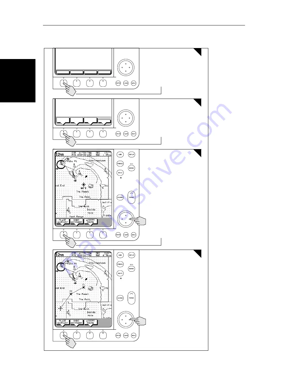
Make and Follow a Route

#

GOTO

SCREEN

ROUTE

FIND SHIP

MAKE

ROUTE

EDIT

ROUTE

CLEAR

ROUTE


MORE¬

2

2.

 Press the soft key

1

3

4

Press the soft key

D4268-1

Press the soft key

1.

 Position Cursor - in this example 

over an existing waypoint

Position Cursor for next waypoint, 
then press soft key. 
Repeat to plot all waypoints in 
sequence.

Summary of Contents for 530

Page 1: ...SL520 530 631 PLUS Chartplotter Display Owner s Handbook Document number 81209_1 Date September 2002...

Page 2: ......

Page 3: ...articular 1 HIGH VOLTAGE The LCD display unit unit contains high voltages Adjustments require specialized service procedures and tools only available to qualified service technicians there are no user...

Page 4: ...ined in this handbook to the best of our knowledge was correct as it went to press However our policy of continuous improvement and updating may change product specifications withoutprior notice Asare...

Page 5: ...al effect that will be seen with all color LCD displays IncommonwithallThinFilmTransistor TFT LCDdisplays thescreenmay exhibit a few less than 20 wrongly illuminated pixels These may appear as black p...

Page 6: ...esigned to the best industry standards for use in the recreational marine environment The design and manufacture of Raymarine equipment and accessories conform to the appropriate Electromagnetic Compa...

Page 7: ...ys 1 10 Pop Up Menus 1 11 Database Lists 1 12 Chapter 2 Getting Started Adjusting the Display 2 1 2 1 Introduction 2 1 Conventions Used 2 1 Simulator 2 1 2 2 Switching the Display On and Off 2 2 Simul...

Page 8: ...Waypoint Details 3 13 Erasing a Waypoint 3 14 Moving a Waypoint 3 14 Using the ST60 or ST80 Navigator Keypad 3 15 3 4 Working with Routes 3 18 Creating a New Route 3 19 Saving the Current Route 3 22 C...

Page 9: ...rsor Echo 4 7 4 6 GPS Setup 4 8 4 7 Data Log Mode 4 10 Chapter 5 Setting Up the System Defaults 5 1 5 1 Introduction 5 1 5 2 Changing the Set Up Parameters 5 2 5 3 System Set Up Parameters 5 4 Data Bo...

Page 10: ...6 1 6 1 Introduction 6 1 Planning the Installation 6 2 EMC Installation Guidelines 6 2 6 2 Unpacking and Inspecting the Components 6 4 6 3 Selecting the Display Unit Location 6 5 6 4 Cable Runs 6 9 Po...

Page 11: ...Display 7 1 EMC Servicing and Safety Guidelines 7 1 7 2 Resetting the System 7 2 7 3 Problem Solving 7 3 Technical Support 7 3 How to Contact Raymarine US 7 4 How to Contact Raymarine Europe 7 5 Worl...

Page 12: ...xii SL520 530 631 PLUS Chartplotter Displays...

Page 13: ...This handbook is organized as follows Chapter 1 provides an overview of the features and functions of the Display This chapter also provides an overview of the controls You should read this chapter t...

Page 14: ...isplay Appendix C defines the SeaTalk and NMEA data that is transferred on integrated systems Appendix D provides a list of abbreviations An Index and warranty information are included at the end of t...

Page 15: ...or BDI navigation data Cursor echo across SeaTalk Choice of orientation Head Up Course Up and North Up The system can be connected to an ST80 Navigator keypad for entry of alpha numeric data Set Up Op...

Page 16: ...to the target waypoint Nav Data This shows nine mono display or sixteen color display data boxes providing navigational data in the units specified in your set up Note that up to 6 of these data boxes...

Page 17: ...el position Speed Over Ground SOG Course Over Ground COG and fix type VES POS DIF FIX or SD FIX Any waypoints you have placed are displayed unless you turned them off in Chart Set Up as described in C...

Page 18: ...ows ON Chart text chart boundaries depth contours navigation marks and land features OFF Caution and routing data CUSTOM Spot sounding light sectors marine features Note The factory default for the CU...

Page 19: ...Place Move Erase and Edit a Waypoint Goto Waypoint or Cursor Create Save Name Edit and Follow a Route Review Route and Waypoint Lists Display vessel s track Save and Name the Track for re call to scr...

Page 20: ...rsor is the cross hair symbol visibleon the display Youmove the cursor using the trackpad anduse it to select a position or item on the chart ThecontrolkeysareshowninFigure 1 2 Theyareback litfornight...

Page 21: ...rsor is outlined by a circle so it is easier to locate on the screen Context Sensitive Cursor Control The cursor is context sensitive When the cursor is positioned over special featureson the display...

Page 22: ...played providing further functions As you press a key a single audio beep confirms the key action If the key press is not valid for the current screen or mode three rapid beeps sound to indicate that...

Page 23: ...s not valid for the current screen or mode three rapid beeps sound to indicate that no response is available If required you can turn the key beeps off as part of your set up procedure see Chapter 5 P...

Page 24: ...p up menus when a database list is on screen a set of associated soft keys is also displayed you use the trackpad to select an item from the list then use the appropriate soft key to edit the item For...

Page 25: ...sequence of numbered steps are indicated by a symbol in the margin Whentheprocedurerequiresyoutopressasoftkey thesoftkeyiconisshown in the margin Simulator The display unit includes a simulator functi...

Page 26: ...only as a backup to official government charts and traditional methods of navigation Whenyouhavereadandunderstoodthecaution presstheCONTINUE soft key The chart is displayed If this is the first time...

Page 27: ...u select the System Set Up Menu and switch off simulator mode when you have finished To view a simulated image 1 Press MENU followed by the SYSTEM SET UP soft key The set up menu pop up is displayed 2...

Page 28: ...Alternatively you can press the trackpad left and right edges to move side ways between the controls to select the soft key 3 If necessary press the soft key to toggle the control ON OFF 4 Use the tra...

Page 29: ...I key to display the soft key controls 2 The LIGHT soft key indicates the brightness level use the trackpad up or down to increase or decrease thesetting You can press and hold thetrack pad to change...

Page 30: ...o set up the display The controls are summarized in the fold out illustration on page 2 8 Selecting the Mode of Operation You use the DISPLAY key to select the full screen mode The following modes can...

Page 31: ...ess either SELECT WINDOWS soft key until the required window is highlighted If necessary this will toggle windows on Press ENTER 3 To toggle windows off press the WINDOWS OFF ON soft key Figure 2 3 sh...

Page 32: ...ld for 2 seconds for full screen display Press soft key to place waypoint at cursor or vessel or display the waypoint list user card menu and asscociated soft keys Press ENTER to finish MARKS MOB Cont...

Page 33: ...djusting the Display 2 9 Selecting the Mode of Operation Figure 2 3 Half Screen Window Options CDI Window SELECT WINDOW WINDOWS OFF ON SELECT WINDOW WINDOWS OFF ON BDI Window Navdata Window SELECT WIN...

Page 34: ...t sensitive cursor on page 1 9 Switching Chart Grid On and Off The Chartplotter display includes grid lines of latitude and longitude which you can use to help determine position on the chart The grid...

Page 35: ...and none are displayed you need to select the ones you require using the system set up menu as described in Section 5 3 System Set Up Parameters You can use the context sensitive cursor to select and...

Page 36: ...Use the context sensitive cursor to change the chart center Automatically re center the vessel using the FIND SHIP soft key Changethechartscaletozoomoutandintoanew areacenteredonthecur sor position T...

Page 37: ...place the vessel and cursor at the center again The status bar indicates vessel position speed and course over ground To release the cursor from homed mode press the trackpad to move the cursor away...

Page 38: ...miles Figure 2 5 Changing the Chart Scale To change the scale quickly press and hold the required arrow on the RANGE key The distance indicator at the left hand end of the status bar is updated whene...

Page 39: ...d to the vessel see Using FIND SHIP onpage 2 13 if thevessel movesoutside an area of available cartography the chart will automatically re scale to the next range with cartography IfPlotter ModeisOn t...

Page 40: ...ssesrequiredtoperformparticular tasks A typical chartplotter screen image is shown for each task The scenarios assume you have read the previous sections of this chapter and that you are familiar with...

Page 41: ...Chapter 2 Getting Started Adjusting the Display 2 17 Typical Chart Scenarios This page intentionally left blank...

Page 42: ...PLUS Chartplotter Displays Place and Goto a Waypoint Place and Goto a Waypoint 1 Press MARKS 2 Position Cursor as required Press the soft key 1 2 3 Press the soft key to go to the waypoint selected by...

Page 43: ...r 2 Getting Started Adjusting the Display 2 19 Place and Goto a Waypoint 4 The vessel navigates towards the target waypoint See 5 3 Working wth Waypoints Go to an individual Target Point page 5 26 D42...

Page 44: ...OTO SCREEN ROUTE FIND SHIP MAKE ROUTE EDIT ROUTE CLEAR ROUTE MORE 2 2 Press the soft key 1 3 4 Press the soft key D4268 1 Press the soft key 1 Position Cursor in this example over an existing waypoint...

Page 45: ...TART XTE WAYPOINT ADVANCE STOP FOLLOW GOTO SCREEN ROUTE FIND SHIP 7 5 6 8 Press the soft key D4268 2a Press the soft key Press the soft key The route becomes the current route The vessel starts to nav...

Page 46: ...FIND SHIP MAKE ROUTE EDIT ROUTE CLEAR ROUTE MORE 2 3 2 Press the soft key 1 4 5 Press the soft key Press the soft key D4269 1 Press the soft key 1 Use the trackpad to move selection bar over required...

Page 47: ...r Passage Plan 6 Change the TIME to HOURS the display indicates it will take 32 minutes to reach the destination You can change the PLANNED SOG the display updates to indicate TIME required at the pla...

Page 48: ...2 24 SL520 530 631 PLUS Chartplotter Displays Review Your Passage Plan...

Page 49: ...uding measuring distances and setting alarms are described in Chapter 4 Safety The chartplotter makes it very easy to place a waypoint and travel towards it However you should always check first that...

Page 50: ...r represents the distance in nautical miles displayed from the top of the chart window to the bottom of the chart window Note You can remove and insert cards while a chart is displayed The chart infor...

Page 51: ...move and move the top of the card to the left to clear the retaining pegs The card will spring half way out enabling you to grip the card and remove it from the slot 3 Remember to close the card cover...

Page 52: ...lay a pop up for all objects and source data automatically when the cursor is over the object symbol or source area Display a pop up for displayed objects when the cursor is over the symbol Do not dis...

Page 53: ...izes fueling sanitation electrical or other maintenance services provided VHF channels monitored and other safety and navigation information In some areas the chart shows symbols for individual facili...

Page 54: ...ich tide information is shown Figure 3 3 Tide Data To select a time use the trackpad to move the cursor to the required time To change the day press PREV DAY DAY or TODAY as required Alternatively pre...

Page 55: ...to highlight the required object then press ENTER i For port services the port service symbols are displayed use the track pad to highlight the required service then press ENTER If you select a port t...

Page 56: ...ll waypoints can be included in a route You can place waypoints using simulator mode before you install the chartplotter on your vessel When you place a new waypoint it is displayed using the default...

Page 57: ...point as described in Editing Waypoints below 2 Press CLEAR or ENTER to remove the place waypoint soft keys To place a waypoint as latitude longitude using the Waypoint List 1 PressMARKS followedbythe...

Page 58: ...current ves sel position or if not available the cursor position To change the position press theLORAN TDssoftkey the WPT POSITION LORAN TDs screenisdis played with it s associated soft key Note Youca...

Page 59: ...meters are edited using the trackpad as described in Editing the Waypoint Details on page 3 13 4 When editing is complete press the ENTER key to save the waypoint or CLEAR to cancel the operation the...

Page 60: ...t details all waypoints in alpha numeric order The selected way point is indicated by the selection bar its position bearing and range are provided 2 Usethetrackpadtomovetheselectionbarupanddownthelis...

Page 61: ...aypoint soft keys are displayed 2 Press the EDIT WAYPOINT soft key The Edit Waypoint soft keys are dis played 3 To edit the symbol press the SYMBOL soft key Use the soft keys shown in the following il...

Page 62: ...try to erase a waypoint that is used in a saved route you are warned WAYPOINT IS USED IN A ROUTE CANNOT BE DELETED To delete a waypoint using the cursor 1 Movethecursoroverthewaypoint until theletters...

Page 63: ...rorthewaypointlistasdescribed above The waypoint soft keys are displayed 2 To edit the waypoint position proceed as previously described in Editing the Waypoint Details on page 3 13 Using the ST60 or...

Page 64: ...int name The selection bar moves to the entry starting with that letter or number If more than one entry begins with that character the selection bar moves to the first one in the list Each time the s...

Page 65: ...keys to move the cursor to the desired character position 2 Press an alphanumeric key until the desired character is displayed Each time you press one of these keys in succession the next character on...

Page 66: ...e route In addition the GOTO default soft key provides various options as described in Section 3 5 Up to 20 routes can be saved in the route database You can then select a route from the database list...

Page 67: ...the chart and change the scale while placing waypoints 1 If necessary move the cursor to the area in which you wish to make the route and select a suitable chart scale 2 Press the ROUTE soft key then...

Page 68: ...first waypoint of a new route is outlined with a square indicating that it will be the target waypoint when the route is activated If selected the waypoint data box is displayed for the target waypoin...

Page 69: ...ay point and press the REMOVE WAYPOINT soft key Notes 1 Awaypointcannotbeusedmorethanonceinaroute thosealready used are displayed in a lighter shade of gray Notes 2 TheINSERTWAYPOINTorREMOVEWAYPOINTac...

Page 70: ...utepop upandtheNAMEROUTE soft keys are displayed as illustrated in Figure 3 6 3 The next available entry on the route list is highlighted If required you can use the trackpad to select another positio...

Page 71: ...press YES 3 If the route has not been saved the SAVE ROUTE soft keys are displayed To clear the route without saving it in the route database press NO To save the route in the database press YES The N...

Page 72: ...ionabout arouteleg movethecursorovertheleguntilthe letters RTE are displayed A Route Leg data box such as the following is displayed To removethedatabox move the cursor away from the route or press CL...

Page 73: ...mation about any route in the database 1 Press the ROUTE soft key followed by MORE then press ROUTE LIST The route list is displayed The selection bar indicates the selected route 2 Usethetrackpadtose...

Page 74: ...the ROUTE soft key followed by MORE then press ROUTE LIST The route list is displayed The selection bar indicates the selected route Press the appropriate soft key ERASE ROUTE or NAME ROUTE 2 If you E...

Page 75: ...o you need to Save the route if you want to keep the changes Inserting a Waypoint into a Route Youcanusethecontext sensitivecursortoinsertoneormorewaypointsinthe current route However if the route is...

Page 76: ...ones Removing a Waypoint from the Route To remove a waypoint from the current route 1 Move the cursor over the required waypoint until the letters WPT are dis played The waypoint soft keys are displa...

Page 77: ...ng joining at a selected waypoint advancing waypoints and restarting XTE Go to an individual point either an existing waypoint or the cursor Stop and Restart Follow Goto An alarm is triggered when you...

Page 78: ...1 Press the ROUTE default soft key followed by MORE The route soft keys are displayed 2 Press the REVERSE ROUTE soft key The current route is reversed on the screen Press ENTER or CLEAR 3 Press the GO...

Page 79: ...g Anyprevious route leg is removed from the screen but waypoints remain Note WhenfollowingarouteusingaSeaTalkautopilot theautopilot willnot turn to the new waypoint until it is accepted at the autopil...

Page 80: ...f off track and want to go straight to your target rather than get back onto the original track To restart XTE 1 Press the GOTO default soft key the Follow Goto soft keys are displayed 2 PresstheRESTA...

Page 81: ...rting position with a dashed line The soft key STOP GOTO is displayed 3 To return to the default soft key display move the cursor away from the waypoint or press ENTER or CLEAR Stop Follow or Stop Got...

Page 82: ...or NMEA and whether youwant totransfer individual waypointsor the complete waypoint and route list You can save the complete Waypoint and Route Lists to a user cartridge in the chart card slot You ca...

Page 83: ...RTE DATA FROM CARD soft key an appropriatewarningandYes Nosoft keysaredisplayed 4 Press Yes to continue or No to abandon the operation and return to the pre vious screen 5 If the operation is success...

Page 84: ...e waypoint transfer press the soft keySTOP RECEIVING WAY POINTS Alternatively press ENTER or CLEAR twice to close the Waypoint List To send the waypoint list on NMEA 1 Display the waypoint list as pre...

Page 85: ...nable you to follow this track on your return voyage the SmartRoute function converts the track or the last segment of a track with breaks into a route which is automatically reversed see SmartRoute o...

Page 86: ...rina whereas in contrast a greater distance interval is best suited to a long haul voyage Refertothesettingguideshownin Figure 3 9todeterminethebest settingfor your planned voyage this is particularly...

Page 87: ...should continue as described in the following section Sav ing and Naming a Track Press CLEAR to abort the Clear Track operation The current track is cleared from the screen and the default soft keys...

Page 88: ...isting track erase a track or show a track you select the track from the track list then press the appropriate soft key as follows 1 PresstheTRACKLISTsoftkey TheTrackListisdisplayed Theselectionbar in...

Page 89: ...viation of the route from the recorded track is displayed To convert the current track into a route 1 Select MAKE INTO ROUTE and press ENTER The current track is converted to a new route and becomes t...

Page 90: ...3 42 SL520 530 631 PLUS Chartplotter Displays SmartRoute...

Page 91: ...ons youmayneedthefollowingadditional data from equipment connected to your system via a SeaTalk or NMEA link IfheadingdataisavailableviabothNMEAandSeaTalk NMEAdatatakespriority Forallotherdata SeaTalk...

Page 92: ...A Ruler data box is displayed showing the bearing and distance from the starting point to the cursor position The character A appears at the cursor location 3 Use the trackpad to move the cursor to t...

Page 93: ...to the previous position To clear the ruler line and ruler data box either Move the cursor over the ruler line until the letters A B are displayed then press CLEAR or Press VRM EBL the ruler soft keys...

Page 94: ...ion or shore obstruction You specify the depth and range of the sector from your vessel You can view a report of the objects that triggered the alarm Countdown The countdown timer has reached zero Ala...

Page 95: ...off track and anchor alarm distances can be set in the range 0 01 to 9 99 nm in steps of 0 01nm Thegroundingalarmdepthcanbesetfrom1to20min1mstepsandcanbe specified to cover a sector at a range from 0...

Page 96: ...Redrawsthechartat1 2nm evenifcartographyisnotavailablebutplotter mode is on Marks the current position with a MOB symbol which replaces any current active waypoint and route Displays the MOB data box...

Page 97: ...cursor in a chart window nor a remote radar cursor in a radar window The following options can be toggled ON or OFF Radar Cursor In displays the cursor from a radar on the chart window default OFF Cha...

Page 98: ...tion angles are used in a triangulation process to calculate position HDOP Horizontal Dilution Of Position is a measure of this accuracy a higher figure signifies greater error In ideal circumstances...

Page 99: ...ncy Boththemenuitemandassociated soft keysshow the currently used differential beacon s frequency in kHz The frequency range available is 283 5kHz to 325 0kHz Bit Rate Both the menu item and associate...

Page 100: ...elect DataLogModethelogisdisplayedfull screen Ifthescreenisfull youusethe trackpad to scroll the list and view further log entries Each line in the log shows Time of log entry Position at time of log...

Page 101: ...Press DISPLAY to select the chart mode then press ENTER The log continues until you return to the data log mode and press STOP LOG TIME POSITION CMG DMG CLEAR LOG STOP LOG 15 30 16 00 16 30 17 00 17...

Page 102: ...4 12 SL520 530 631 PLUS Chartplotter Displays Data Log Mode...

Page 103: ...you press the MENU key In most cases you will only need to use the MENU key options when you first set up your system However you may decide to change the way you have customized some aspects such as...

Page 104: ...se the trackpad to move the selection bar up and down the list An arrow is displayed at the top or bottom right hand corner if you can scroll the list to display further parameters As each line is hig...

Page 105: ...e required values press ENTER to clear the menu and return to the set up soft keys 6 Press ENTER MENU or CLEAR to clear the soft keys and return to the default display You can return all the settings...

Page 106: ...OFF or ON OFF or ON OFF or ON OFF or ON OFF APP TRUE or BOTH OFF LAT LON or RNG BRG TTG OFF or ON OFF or ON OFF or ON OFF or ON OFF WIND WPT or BOTH OFF or ON OFF or ON OFF OFF OFF OFF OFF OFF OFF OFF...

Page 107: ...IN S T CURSOR OUT CURSOR ECHO LOCAL OFF or ON Not valid for SL520 530 631 PLUS display OFF or ON Not valid for SL520 530 631 PLUS display OFF OFF OFF ON DATE FORMAT DD MM YY MM DD YY MM DD YY TIME FO...

Page 108: ...layed This is indicated in the status bar after the heading value Cursor Reference The mode of the bearing data displayed for the cursor readout The bearing information can be displayed in either of t...

Page 109: ...ater on the assumption that your vessel and the object are both subject to the same tide and wind effects Autopilot Pop Up Thisoptioncontrolswhetherornottheautopilotpopupisdisplayed Whenset to ON if t...

Page 110: ...but no SeaTalk variation is available then variation is taken from NMEA 3 A calculated variation value using position data if no SeaTalk or NMEA value is available 4 The current manual variation value...

Page 111: ...origin This means that you could move the cursor over a targetontheradardisplay andchecktheidentityofthetarget bylookingatthe radar cursor position on the chartplotter Press the CURSOR ECHO soft key...

Page 112: ...EDIUM or LOW Compass Set Up This option is used to calibrate a Raymarine heading sensor such as the Pathfinder Smart Heading System Controls are provided for Linearise Compass which detects and correc...

Page 113: ...SCREEN soft keys see Customizing the Screen Presentation Options on page 2 10 The following features can be set using Customize Chart factory default settings are shown in bold type chart text on off...

Page 114: ...s normally North Up but can be changed to Course Up or Head Up if heading data is available The orientation modes give the following displays North Up The chart is displayed with north upwards As you...

Page 115: ...mbol lets you select the symbol you want used for waypoint display Vectors Heading Tide and Course Over Ground vectors can be displayed as a line from your vessel The length of the vector is determine...

Page 116: ...t by moving the cursor to the known vessel position This offset is applied to all incoming position data The default offset value is zero When position offset is switched on all displayed vessel posit...

Page 117: ...n 6 7 To connect your display to other equipment follow the guidelines in Section 6 8 and Section 6 9 taking particular care to ensure the correct polarity of the SeaTalk supply Figure 6 1 Typical Cha...

Page 118: ...gn and manufacture conforms to the appropriate Electromagnetic Compatibility EMC standards but correct installation is required to ensure thatperformanceisnotcompromised Althougheveryefforthasbeentake...

Page 119: ...so is detailed in the installation manual If a suppression ferrite is attached to a cable this ferrite should not be removed If the ferrite needs to be removed during installation it must be reassemb...

Page 120: ...PLUS SL631 PLUS Handbook Quick Reference Card Chart 81209 86079 SL520 530 631 PLUS SL520 530 631 PLUS 7 Mounting bracket assy Trunnion knobs x2 7 Flush Mount Kit 10 4 Mounting bracket assy 10 4 Flush...

Page 121: ...ow cable connections to the rear panel connectors avoiding tight bends in the cable Interference The selected location should be far enough away from devices that may cause interference such as motors...

Page 122: ...rtplotter Displays Selecting the Display Unit Location Figure 6 3 7 Mono LCD Display Dimensions DISPLAY GAIN VRM EBL MULTI MARKS ALARMS RANGE ENTER CLEAR MENU POWER Weight 1 2 Kg 2 6 lbs Compass Safe...

Page 123: ...NTER CLEAR MENU POWER Weight 7 7 lbs 3 5 Kg Compass Safe Distance 39 in 1 m 10 51 in 267 mm 0 95 in 24 3 mm 6 89 in 175 mm 0 4 in 10 mm 7 3 in 185 mm 8 1 in 205 2 mm 8 8 in 223 6 mm 3 15 in 80 mm 6 3...

Page 124: ...ons D5066 1 11 5 in 292 mm 3 82 in 97 mm 6 38 in 162 mm cable clearance Weight 12 65 lbs 5 75 kg Compass Safe Distance 39 in 1 m 12 9 in 328 mm 9 7 in 246 mm 0 87 in 22 1 mm 7 88 in 200 mm 1 7 in 43 m...

Page 125: ...isplayunit Thishasacon nector plug at one end for connecting the display unit and 7 wires at the otherendfor connectingthepowersupplyandoptional NMEA inputs see Section 6 8 Integrated Systems SeaTalk...

Page 126: ...Mounting 1 Loosen the knobs and remove the mounting bracket from the display unit 2 Mark the locations of the mounting bracket screw holes on the mounting surface 3 Use the screws supplied to attach...

Page 127: ...is required drill four 3 16 in 5 mm holes as indicated on the template Screw the studs into the holes provided at the rear of the display 7 Connect the DC power cable inter unit cable and any other a...

Page 128: ...nection to the display should be made at either the output of the battery isolator switch or at a DC power distribution panel Raymarine recommends that power is fed directly to the display via its own...

Page 129: ...em Power NMEA Input for 12 V 24 V or 32 V DC power connection two NMEA 0183 inputs and one RF ground screen connection Figure 6 7 Chartplotter Display Connector Panel Thefollowingsectionsdetail the di...

Page 130: ...ower leads are connected for correct polarity Switch off the display unit before you remove the power cord The RED wire must be connected to the feed from the positive battery terminal and the BLACK w...

Page 131: ...king arrange ments as specified are in place All connections have been made All connecting wires are secured and protected as necessary Note If you are the boat owner and have performed the installati...

Page 132: ...going to sea to make sure that it is not affected by radio transmissions engine starting etc D3650 6 SYSTEM SET UP MENU DATA BOXES BEARING MODE CURSOR REFERENCE CURSOR READOUT DAY NIGHT HELP SOFT KEYS...

Page 133: ...wered from the display s SeaTalk interface It must be powered from the ship s supply or via a SeaTalk bus Ensure correct polarity of the SeaTalk connection For systems where the ship s power source is...

Page 134: ...nder uses this data if this data is not on SeaTalk from other instruments it is transmitted by the Fishfinder For details of received data refer to the table in Appendix C SeaTalk and NMEA Data Receiv...

Page 135: ...MC CE conformance The ferrite must be clipped to the cable as close to the connector as possible 2 Thedisplaydoesnotsupply12VviatheSeaTalkconnector neitherdoesthe SeaTalk connector require 12 V to ope...

Page 136: ...angle and wind speed data TheNMEA0183standardcarriessimilarinformationtoSeaTalk However it has the important difference that one cable will only carry information in one direction For this reason NME...

Page 137: ...g supplying power to a flux gate compass and routing the compass data to the display NMEA In connection or alternatively for connecting a NMEA GPS system The junction box includes SeaTalk cable and c...

Page 138: ...Out Set Up on page 5 9 The SeaTalk input output connection is detailed in SeaTalk Connection on page 6 19 The NMEA output connector is a 4 pin connector as illustrated below The 1 5 m NMEA OUT cable h...

Page 139: ...sed to other instruments You can prevent NMEA heading data being bridged onto the Seatalk bus refer to Bridge NMEA Heading on page 5 8 Note TotransferNMEAdata ortoconvert thedata thedisplaymustbepow e...

Page 140: ...elsymbolwhichiscor rectly positioned at the center of the chart display 3 Insert a chart cartridge for the area of your vessel Use the RANGE key to zoom in to check that the chart data is being dis pl...

Page 141: ...fore limited to the following periodic checks Wipe the display clean with a damp cloth ensure power is off Examine the cables for signs of damage such as chafing cuts or nicks Check that the cable con...

Page 142: ...theequipment from being affected by external influences In general this will not damage the equipment but it can leadto spuriousresetting action or momentarily may result in faulty operation 7 2 Rese...

Page 143: ...n If youstill havea problem after referring to thetable below contact your local dealer national distributor or Raymarine Technical Services Department for further advice Always quote the product seri...

Page 144: ...200 to verify your requirements For Product Repair and Service In the unlikely event your Raymarine unit should develop a problem please contact your authorized Raymarine dealer for assistance The dea...

Page 145: ...om Accessories and Parts Raymarine accessory items and parts are available through your authorized Raymarine dealer Please refer to the lists of component part numbers and optional accessories in the...

Page 146: ...7 6 SL520 530 631 PLUS Chartplotter Displays Worldwide Support...

Page 147: ...full brightness 30W max consumption with full brightness Environmental Op Storage Temp Range mono color Humidity limit Waterproof to CFR46 suitable for external mounting 10 C to 70 C 10 C to 50 C up t...

Page 148: ...netic Head up or Course up Waypoints 1000waypointsenteredviacursor lat lon rangeandbearingfrom present position or at vessels position 16 character name can be assigned Additional storage available on...

Page 149: ...oss Track Error Heading Wind Date Log Trip Pilot Status Temperature Man Overboard and cursor position NMEA Input NMEA 0183 GLL GGA GLC GTD VTG BWC BWR RMA RMB RMC XTE VHW HDG HDM HDT DBT DPT APB VLW M...

Page 150: ...A 4 SL520 530 631 PLUS Chartplotter Displays SL520 530 631 PLUS Displays...

Page 151: ...to switch the customized icons off on The factory default for the CUSTOM options is on The chart features controlled from the Customize Chart menu are grouped as detailed below some groups are sub di...

Page 152: ...rritorial sea baseline Submarine transit lane Territorial sea area Restricted area SeaPlane landing area Military practice area Tracksand Routes Deep water route part Deep water route cen terline Fair...

Page 153: ...Lake shore Cultural Features Airport area Built up area Railway Road crossing Road part Runway Sloping ground Square Cable overhead Fence Pipeline overhead Pylon Telepheric Tunnel entrance Building re...

Page 154: ...escue station Signal station traf fic Signal station warning Port Information Port area Harbour master Coast Guard Police Customs Health emergency Post office Yacht club Boat yard Accessories Electric...

Page 155: ...uction installation Offshore platform AREAS LIMITS No data area CARTOGRAPHIC OBJECTS Incomplete survey area NATURAL FEATURES Ice Ice area Pingo COMPOSITE OBJECTS Airport Anchorage Channel edge Deep wa...

Page 156: ...B 6 SL520 530 631 PLUS Chartplotter Displays C MAP Chart Card Features...

Page 157: ...RMB XTE Depth SeaTalk DBT DPT Apparent Wind Angle and Speed SeaTalk MWV relative Boat Speed Through Water SeaTalk VHW Total Log and Trip Log SeaTalk VLW Water Temperature SeaTalk MTW Average Boat Spee...

Page 158: ...A Out Position LAT LON GGA GLL RMC RMA Position Loran C TD s RMA Speed Over Ground and Course Over Ground RMC VTG RMA Waypoint Data RMB APB BWC BWR Depth Apparent Wind Angle and Speed Boat Speed Throu...

Page 159: ...Cathode Ray Tube CTR Center dB deciBels DC Direct Current DMG Distance Made Good DR Dead Reckoning EBL Electronic Bearing Line EMC Electro Magnetic Compatibility ETA Estimated Time of Arrival FCC Fede...

Page 160: ...MEA National Marine Electronics Association POS Position of vessel RF Radio Frequency Rng Range rpm Revolutions Per Minute SSB Single Side Band SHM Ships Heading Marker SOG Speed Over Ground STC Sensi...

Page 161: ...rth Up 5 12 Scale 2 12 2 13 3 2 4 6 Simulator 2 1 2 3 5 10 Chart Card 1 3 1 5 Object Information 3 4 5 11 5 13 Chart Grid On and Off 2 10 Chart Master 1 2 Chartplotter Control Functions 2 12 Display O...

Page 162: ...ase List 1 8 1 12 Route 3 15 3 18 3 22 3 25 Retrieving 3 23 Track 3 39 Waypoint 3 8 3 9 3 13 3 14 3 19 3 32 Date Data Box 5 4 Date Format 5 5 5 9 Datum Selection 5 11 5 13 Day Night 5 4 5 6 Dedicated...

Page 163: ...7 5 US 7 4 High Voltage 1 iii I Identifying Objects with Cursor Echo 4 7 Installation Cable Runs 6 2 6 9 EMC Conformance 6 16 EMC Guidelines 6 2 Integrated System 6 17 Location 6 2 6 5 Integrated Syst...

Page 164: ...Waypoint Scenario 2 18 Placing a Waypoint 3 8 3 9 3 19 Plotter Mode 2 15 5 11 5 12 Pop up Menus 1 8 1 11 Port Data 3 4 3 5 Position a Waypoint 3 8 3 13 Position Data 1 4 4 1 4 6 Position Data Box 5 4...

Page 165: ...Ground Data Box 5 4 Specification Display A 1 Speed Data 4 6 Speed Data Box 5 4 ST60 80 Navigator Keypad 3 8 3 15 3 17 Status Bar 1 5 Stop Follow 3 29 3 33 Goto 3 29 3 33 Track See Clear Track Switchi...

Page 166: ...a User Cartridge 3 34 MOB 4 6 Moving 3 8 3 14 3 18 3 27 Naming 3 8 3 13 Numbers 5 11 5 13 Placing 3 8 3 9 3 19 Position 3 8 3 13 Removing from a Route 3 18 3 28 Saving to a User Cartridge 3 34 Select...

Page 167: ...showing date place of purchase and serial number must be made available to Raymarine or authorized service agent at the time of request for Warranty service In cases where a Raymarine certified insta...

Page 168: ...rcraft rental subsistence customs shipping and communication charges etc Travel costs mile age and time in excess to that allowed must have prior approval in writing TO THE EXTENT CONSISTENT WITH STAT...

Page 169: ...der Services Telephone 1 800 539 5539 Ext 2333 or 1 603 881 5200 Ext 2333 Customer Support Telephone 44 0 23 9271 4713 Fax 44 0 23 9266 1228 Technical Support Telephone 1 800 539 5539 Ext 2444 or 1 60...

Page 170: ......

Reviews: