6
Manual No. 016-0171-148
73
Basic Operation
The following information is displayed on this screen:
1.
Application information
2.
Selected product
3.
Control mode
4.
Target rate
5.
Display options
Touch the green check mark to return to the Guidance screen.
To view and setup additional settings for each product, touch the green arrow to display the Product Control
Configuration screen. Refer to the
section on page 98 for more information on product control
configuration.
Application Information.
The Application Information displays the following information for the selected
product:
•
Area per hour
•
Pressure or fan speed - if an optional pressure transducer (P/N 422-0000-059) or fan speed sensor
(P/N 063-0171-277) has been installed
•
Volume per minute
•
Control status
•
If a PWM or PWM Close valve is setup to control the selected product, the duty cycle of the PWM valve
appears in this area.
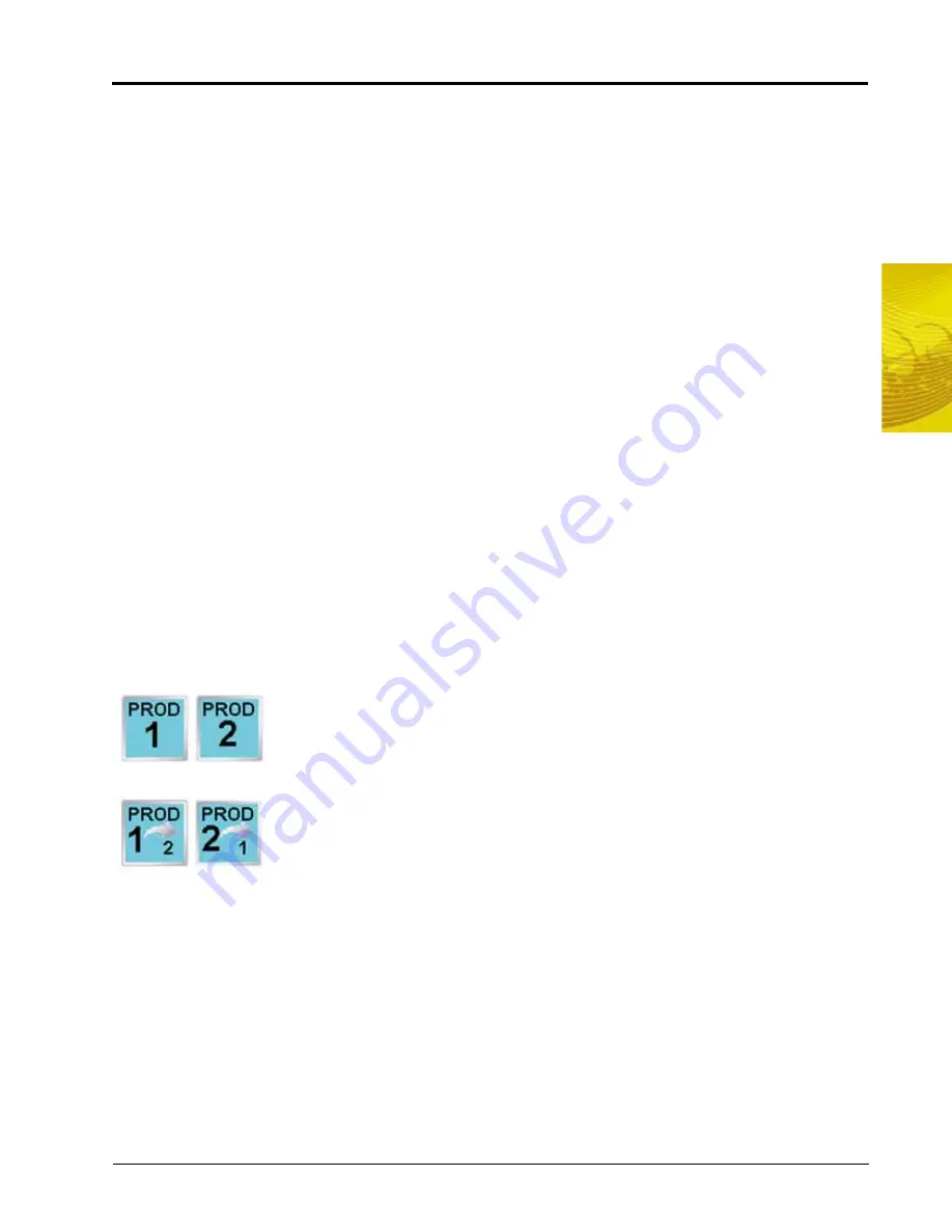
Selected Product.
The selected product icon displays the current node or control channel for which the in job
product settings are displayed. If multiple products are enabled during the job setup, the selected product icon
may also be used to cycle through enabled nodes or control channels to configure other nodes or control
channels without returning to the Guidance screen.
If only one product is enabled for the current job, the selected product icon will display
similar to icons shown to the left. The displayed product node or control channel is
always selected during the active job.
If additional products are enabled for the current job, the selected product allows the
operator to cycle through the enabled nodes or control channels.
Before modifying any settings displayed on the screen, check that the correct product
node or control channel is selected.
Control Mode.
Use the control mode to set the mode of operation for the product control valve. Select:
•
Off to turn off product control for the selected product.
•
Manual to control the actual application rate manually.
•
Automatic to allow the field computer to control product application rates automatically.
Note:
If a CAN Switch Box is installed with the field computer, the field computer will display the control
mode set using the Product Control switches on the switch box. Refer to the CAN Switch Box
Installation and Operation Guide for additional operation of the CAN Switch Box.
Target Rate.
The name and target rate of the selected product are displayed on a button on the In Job Product
Configuration screen. Touch this button and use the displayed keypad to adjust the target rate.
Product 1
Only
Product 2
Only
Cycle to
Product 2
Cycle to
Product 1
Summary of Contents for Envizio Pro
Page 1: ...Software Version 3 2 Envizio Pro Envizio Pro II Installation Operation Manual...
Page 36: ...Chapter 3 26 Envizio Pro and Envizio Pro II Installation and Operation Manual...
Page 148: ...Chapter 7 138 Envizio Pro and Envizio Pro II Installation and Operation Manual...
Page 158: ...Chapter 8 148 Envizio Pro and Envizio Pro II Installation and Operation Manual...
Page 174: ...Chapter 9 164 Envizio Pro and Envizio Pro II Installation and Operation Manual...
Page 178: ...Chapter 10 168 Envizio Pro and Envizio Pro II Installation and Operation Manual...
Page 184: ...Chapter 11 174 Envizio Pro and Envizio Pro II Installation and Operation Manual...
Page 210: ...Appendix D 200 Envizio Pro and Envizio Pro II Installation and Operation Manual...
Page 230: ...Index 220 Envizio Pro Envizio Pro II Installation Operation Manual...


