VIDEO VBOX LITE MANUAL
Page | 63
22 December 2009
Now we need to make the Dial markers, we make the marker points first as these give us the exact locations of the
numbering when we add those to the gauge face.
It is a matter of preference of how big, what colour, and where on the gauge they are. For this example we’ll keep it
simple and create a big marker for the numbers, and a smaller marker for the intermediate markers both in black.
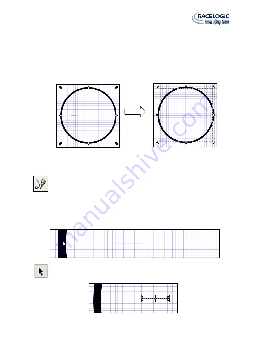
Click on the inner circle twice, you should see the outline box arrows change shape and direction and a cross appear in
the middle of the circle. This is the centre point (and centre rotation point) of the circle and can be used as a guide to
the centre lines of the circle.
Zoom into the Screen using the ‘Zoom’ button, or holding the ‘CTRL’ key and moving the mouse scroll wheel up and
down to zoom in and out.
Click the Bezier curves and straight lines button.
Click a point on the centre line of the circle and draw a line, the width of the line can be changed in the ‘width box in
the top menu bar. I have used a width of 50 pixels and a height of 1.
NB:
You may want to turn off grid snapping to allow you to align the marker correctly with the grid. To do this go to
‘File
Document Properties’ then select the ‘Snap’ tab and turn off ‘Enable Snapping’.
If not already selected choose the ‘select and transform objects’ button , then select the line you have just
created. You should see something like the picture below.


