background image

 
VIDEO VBOX LITE MANUAL 


Page | 34 


22 December 2009 

Scenes 

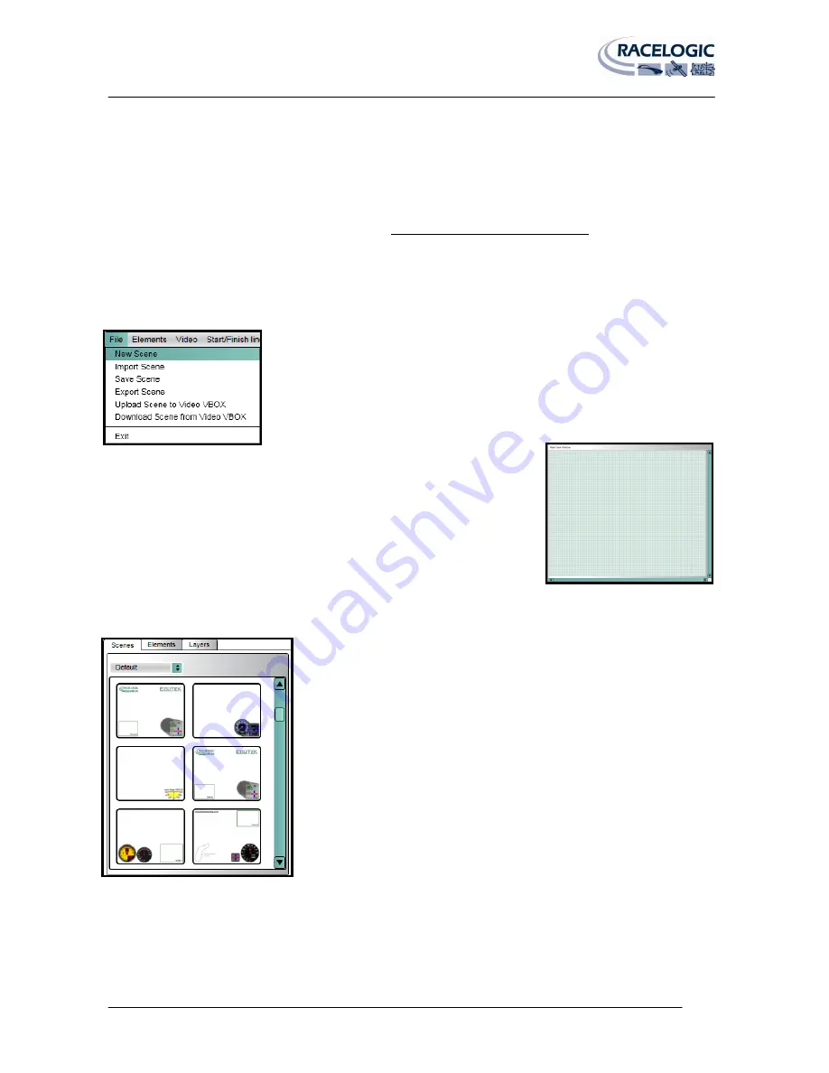
Scenes define how the video overlay will look when the Video VBOX LITE is recording the video file. The Scenes tab in 
the Element browser window contains all of the currently defined Scenes for the Video VBOX LITE. 

This product ships with a default graphical scene. To get more scenes free of charge please 

register your unit here: www.videovbox.co.uk/register 


Creating a New Scene 


To create a new Scene from the bottom up, click the File menu and select ‘New 
Scene’. 


This will clear the current scene in the Main View Window and open a blank 
scene. 


Selecting an Existing Scene 


Scenes are categorised using a theme e.g. Default, Retro, Classic etc, and the 
dropdown list presents the user with a list of currently defined themes. Select a 
theme to display all available Scenes in the preview window. 


Summary of Contents for VBOX LITE

Page 1: ...VIDEO VBOX LITE HARDWARE SOFTWARE MANUAL Issue 1 22 December 2009...

Page 2: ...VIDEO VBOX LITE MANUAL Page 2 22 December 2009 This page intentionally left blank...

Page 3: ...ile created This guide enables you as a new Video VBOX LITE user to quickly get started and introduces you to key features of the hardware and software It describes how to use the Video VBOX LITE and...

Page 4: ...ing Started with your Video VBOX LITE 12 Connections 12 LED Indicators 12 Displaying Data with the OLED display 13 VVBL Data Logging 14 Standard Channels 14 Single CAN channel Logging 14 Lap Timing Pa...

Page 5: ...Timing Parameters 24 Creating Start Finish Lines and Splits 25 Creating Circuit Overlays 27 Displaying DriftBox Parameters 28 Performing a GPS Engine Coldstart 28 Software Overview 29 Recommended Sof...

Page 6: ...a Scene 39 Saving the Scene 41 Uploading a Scene to the Video VBOX LITE 42 Using the Software 42 Using the SD Card 42 Downloading a Scene from the Video VBOX LITE 42 Exporting a Scene from the Softwa...

Page 7: ...the Video VBOX LITE firmware 71 APPENDIX 4 How to install the USB Drivers in VISTA 72 APPENDIX 5 Troubleshooting Guide 76 APPENDIX 6 Video VBOX LITE Specification 79 Outputs and Accuracies 79 Graphics...

Page 8: ...metal ring to lock in place Then plug the cigarette lighter adapter into your vehicle NOTE The Video VBOX Lite will take about 35 seconds to start at which point the unit will beep to indicate it has...

Page 9: ...t the box or re insert the SD card IMPORTANT SD Card Removal NEVER eject the SD card if the RECORD LED is showing you will lose video To stop recording either come to a halt press the RECORD button or...

Page 10: ...th Measure your acceleration figures top speed mile etc What can you customise on the Video VBOX LITE User configurable graphical overlays logos gauges bar graphs circuit plots lap times distance text...

Page 11: ...igher to run The installation CD contains the required NET installation package NB In order to play back the AVI files recorded by the Video VBOX LITE the XVid Codec pack must also be installed The in...

Page 12: ...to the Video VBOX LITE This is necessary because on power up the Video VBOX LITE will look for a connected GPS antenna and automatically adjust its gain for optimum performance LED Indicators There ar...

Page 13: ...ault to the last mode used so if you have set Start Finish Split lines in the scene and the OLED was last used for lap timing the OLED will automatically display the lap timing information for the cur...

Page 14: ...ameter and the use of the CAN parameter in the Video Overlay 1 CAN channel Video VBOX LITE models RLVBVD10LT RLVBVD10LT1 and RLVBVD10LT2 For more information on how to log the CAN parameter and use th...

Page 15: ...fferent positions when each individual field is captured These artefacts may be more visible when interlaced video is displayed at a slower speed than it was captured or when still frames are presente...

Page 16: ...nd the green RECORD light will go off If Log continuously is selected press the RECORD button on the front of the unit This will ensure that the current file is closed and will help to safeguard again...

Page 17: ...3119 15712 Split 59 00605 3119 22063 59 00951 3119 21784 Split 59 06469 3119 32464 59 06773 3119 32034 Split 58 99396 3119 35256 58 99286 3119 34767 Split 59 32845 3119 34939 59 31972 3119 35026 Spli...

Page 18: ...nnel will be available for use in the Scene NB The example on the right shows the empty CAN channel of a Video VBOX LITE 2 The user has the option of loading the Racelogic supplied Vehicle CAN Databas...

Page 19: ...ser must then choose the CAN parameter to be used by the Video VBOX LITE Clicking on the parameter name will list the CAN parameter field information to the right of the window By ticking the checkbox...

Page 20: ...ogic provided Video VBOX LITE CAN Database their own CAN dbc database file or cancelling the load operation 3 Once the CAN database has been selected the user must then choose which CAN parameter is t...

Page 21: ...lly configured to send out an acknowledge pulse over the CAN network This is necessary for any modules to correctly communicate with the Video VBOX LITE NB Caution should be taken if the box has been...

Page 22: ...aps inside a fuse box by the driver s knee Your OBD connector will probably be in plain view but some connectors are covered NB If the connection needs to be made using a bare wire interface with the...

Page 23: ...channels of the Input Modules Initially all of the channel buttons will be greyed out this indicates that the parameter is currently not associated to an Element in the scene and not being logged to...

Page 24: ...for use with the Video VBOX LITE To ensure the Mini Input Module has the correct settings for use with the Video VBOX LITE the correct settings must be uploaded into the MIM using the Stand Alone Set...

Page 25: ...g cursor position In addition to the start finish up to 20 split points can also be set in the software To define the split points press the S key at the desired cursor location or select the Set Spli...

Page 26: ...o create a split file in VBOX Tools for use at a circuit where split points are placed on areas of track which pass very close to each other it may be necessary to reduce the gate width accordingly th...

Page 27: ...rossed Load the logged file from the media using File Load All Save using Save select Save as type and pick Circuit file cir Creating an Overlay File For a single direction Special Stage Drive to the...

Page 28: ...can be useful if the Video VBOX LITE is having trouble locking onto satellites which typically occurs if it is the first time the Video VBOX LITE has been used it has not been used for several weeks...

Page 29: ...oftware Tools Listed below are a few suggestions for some software packages tools that can be used in conjunction with the Video VBOX LITE setup software to play the recorded video files create and ed...

Page 30: ...ed scene from a file New Scene This option allows the user to create a new customised Scene from scratch A list of the 5 most recently used Scene files are also listed under recent scenes below the me...

Page 31: ...indow Three tabs are available in the browser window Scenes Elements and Layers These tabs contain thumbnail previews of the Scenes and Elements that have been created and saved for use on the Video V...

Page 32: ...are or uploaded to a connected Video VBOX LITE Save Scene This saves the current scene which will then become available within the browser window The user will be prompted for a name for the file When...

Page 33: ...ort Element This allows the user to Export an Element to a saved ELM file Save Element If an Element has been modified or newly created then it must be saved in order to use it in the future Clicking...

Page 34: ...get more scenes free of charge please register your unit here www videovbox co uk register Creating a New Scene To create a new Scene from the bottom up click the File menu and select New Scene This...

Page 35: ...channel is set in the scene the software will not allow it to upload to the VVB LITE The Four Camera box should be checked if using a four camera unit to allow all of the associated PIP and scene opt...

Page 36: ...camera quadrant Picture in Picture will allow up to three PIP elements to be displayed in the overlay Depends on VVB LITE model and number of available cameras four camera option only available on Vi...

Page 37: ...lows you to categorise elements you have created by filtering the Element files by type e g Classic Retro All For example selecting the Retro theme will show a graphical preview of all of the Gauges s...

Page 38: ...nt at the top of the list 0 is the element on the top layer Likewise the Element at the bottom 7 of the list is the Element on the bottom layer When you are creating a multi element gauge each new Ele...

Page 39: ...elements in a Scene In order to move multiple Elements it is necessary to first group them All elements belonging to that group will then be moved at the same time Grouping of elements still allows a...

Page 40: ...t Right clicking on the highlighted elements and selecting Add to group opens the select group Pop up window which lets you name the group to be created Selecting Layers from the Preview Window It is...

Page 41: ...s allows you to categorise Scenes you have created by filtering the Scene files by type e g Default Classic Retro All You can create new themes depending on the type of Scene you have created or defin...

Page 42: ...m deleting the scene file from the SD card after successful upload To do this a text file must be created in the same directory as the scene file the text file should have the title no delete scene tx...

Page 43: ...of full screen PAL is 720 X 576 pixels if this is divided by three each grid section is 240 X 192 pixels Depending on how much of the screen you want to fill up with a gauge for example will depend o...

Page 44: ...down menu listing the different types of Element it is possible to add to the Scene e g Gauge Image Picture In Picture etc Selecting Picture in Picture will add a Picture In Picture Window to the Main...

Page 45: ...to the Main View Window The Element Properties window will now reflect the properties of the Gauge Element just created There are two main components of a Gauge the background and the Needle These com...

Page 46: ...n Once the Gauge face has been selected and the minimum and maximum gauge range and the displayed parameter have been chosen the next step is to select a Gauge needle Needle When the background has be...

Page 47: ...precisely centre the crosshairs at the centre of the Gauge If you decide later that you are not happy with the centre point location clicking the Zero Needle button will reset the needle location all...

Page 48: ...ow repeat the steps for the maximum rotation point Click and drag the slider button to rotate the needle around the rotation point until the needle is located at the maximum point on the Gauge scale C...

Page 49: ...types of Element it is possible to add to the Scene e g Gauge Image Picture In Picture etc Selecting Single Bar Graph will add a blank scratchpad to the Main View Window The Element Properties window...

Page 50: ...ch as a thermometer this will need to be changed to bottom to top Clicking on the Fill Direction drop down menu allows the user to select between fill directions of left to right right to left bottom...

Page 51: ...ecting Double Bar Graph will add a blank scratchpad to the Main View Window The Element Properties window will now reflect the properties of the Single Bar Graph Element just created There are five ma...

Page 52: ...Setting the Bar Fill Direction The fill direction is already set by default for the Bars in a Double Bar Graph The fill direction for the bars is as follows Left Negative Bar Right to left Right Posi...

Page 53: ...The circuit overlay file contains the latitude and longitude data of a track and when used with a position indicator will show the live position of the vehicle Circuit maps of many of the popular trac...

Page 54: ...the Text Element just created 2 Selecting the Parameter This selects the parameter to be displayed by the Text Display The user has the option of choosing one of the GPS parameters such as speed If a...

Page 55: ...any of the lap timing parameters from the following list Current Lap Current Lap Number Current Lap Time Current Lap Time Completed Laps Number of Completed Laps Last Lap Time Time of last lap Best La...

Page 56: ...r be downloaded from the Racelogic website http www driftbox com dlfiles html or created by the user using the VBOX Tools software which is installed along with the Video VBOX LITE Setup software See...

Page 57: ...ow The Element Properties window will now reflect the properties of the Static Label just created 2 Defining the Text The text box defines what is displayed by the Static Label Typing into this box up...

Page 58: ...it is possible to add to the Scene e g Gauge Image Picture In Picture etc Selecting Static Image will add a new Text Element to the Main View Window The Element Properties window will now reflect the...

Page 59: ...such as gauges can be customised by changing the Bitmap used for the face or needle or both and also the range displayed by the gauge If these changes are to be permanent and the Element used again wi...

Page 60: ...creating images suitable for use with the Video VBOX LITE One which has been used extensively by Racelogic for the quick and easy creation of gauges is an open source application called Inkscape This...

Page 61: ...f you need to move the circle or any other item you will need to press the Select and Transform Button before you can move the circle Pressing the F1 key has the same effect If you need to resize the...

Page 62: ...is to improve contrast between the recorded video and the gauge On the Opacity slider move it to the far right to 100 as our first gauge will be completely opaque Now click on the Stroke Style tab Ent...

Page 63: ...tation point of the circle and can be used as a guide to the centre lines of the circle Zoom into the Screen using the Zoom button or holding the CTRL key and moving the mouse scroll wheel up and down...

Page 64: ...ware Before we rotate the marker we have to select the rotation point for the marker which is also the centre point of the gauge Click twice on the marker until the corner arrows change to rotation ar...

Page 65: ...markers can now be duplicated and will rotate 15 degrees Click on the marker until the rotation cross appears then right click and select Duplicate or press CTRL D Now while holding the CTRL key clic...

Page 66: ...grid snapping to allow you to align the marker correctly with the grid To do this go to File Document Properties then select the Snap tab and turn off Enable Snapping the marker can then be moved and...

Page 67: ...e used the Iperion font then click on apply in the bottom right You should now see an empty text box displayed with a flashing cursor bar enter the value zero in this text box While the text box is in...

Page 68: ...s exported Click the Browse window and choose a name and location for the image then click export The image can now be loaded into the Video VBOX LITE software for use as a gauge background The above...

Page 69: ...ear data where the plot of the data produces a straight line 1 Obtain full scale voltage values Assume that the voltage read by the Input Module is 0 5 volts when the pedal is not being pressed and 5...

Page 70: ...sides of the equation gives us C 11 11 6 The full equation for the line Substituting these values back into the equation again gives us the full equation of the line which passes through our two point...

Page 71: ...VBOX LITE Once the upgrade is complete the Video VBOX LITE will beep twice and resume normal operation Once the upgrade is complete the upgrade file will be erased and a report file will be generated...

Page 72: ...a 1 Right Click on Computer and select properties Select Device Manager in the top left of the window then connect the powered Video VBOX LITE to the computer via the supplied CAB USB cable 2 Windows...

Page 73: ...d then select Continue In the bottom Right of the screen you will be able to see the following pop up by clicking on the button 6 Wait until the driver installation process fails the following pop up...

Page 74: ...ch contains the VVB drivers and select next C Program Files Racelogic Drivers General Comms Drivers 9 You will get a warning message informing you that Windows cannot verify the publisher of this driv...

Page 75: ...Manager you should see that the Video VBOX LITE has been successfully installed on one of the COM ports and no longer has the yellow warning triangle next to it 12 It should now be possible to connec...

Page 76: ...PS equipment a clear sky view is important Objects in the surrounding area such as tall buildings or trees can block the GPS signal causing a reduction in the number of satellites being tracked or int...

Page 77: ...p file on an SD card and insert into the unit If this still does not cure the problem contact support racelogic co uk Only Audio is present during playback When a video file is played back and only th...

Page 78: ...the Video VBOX LITE powered up in a static location where the antenna has an unobstructed view of the skies until the GPS LED becomes solid green Once the Video VBOX LITE has downloaded the new almana...

Page 79: ...e 10Hz Speed 0 2km h Position 5m day to day 0 5m lap to lap Height 10m Lateral Acceleration 0 5 Longitudinal Acceleration 0 5 Radius of Turn 5cm Distance 0 05 Velocity Accuracy 0 2 Km h averaged over...

Page 80: ...rror Probable 95 CEP Circle Error Probable means 95 of the time the position readings will fall within a circle of the stated diameter Outputs CAN Bus Bit rate 125 kbit s 250kbit s 500kbit s 1Mbit s s...

Page 81: ...xt and images Choose from the internal GPS parameters or external CAN Serial parameters Standard library of gauges fonts etc User definable gauges fonts etc Resolution Options DVD 720 x 576 at 25 fram...

Page 82: ...est RS232 Custom streams can be accommodated send enquiries to Racelogic USB 2 Video streaming for camera set up preview SD card reading and setting parameters via a PC Environmental and Physical Envi...

Page 83: ...Satellites in view 3 then only Identifier 0x301 transmitted and bytes 2 to 8 are set to 0x00 2 Time since midnight This is a count of 10ms intervals since midnight UTC 5383690 53836 90 seconds since m...

Page 84: ...VIDEO VBOX LITE MANUAL Page 84 22 December 2009 Unit Dimensions 580 TVL Camera 21mm 420 TVL Camera 19mm...

Page 85: ...8V Connector 3 CAM2 Pin I O Function 5 I O Ground 7 I Video input 3 O Camera Power 8 18V Connector 4 CAN Pin I O Function 1 O RS232 TxD For future expansion 2 I O CAN High 3 I O CAN Low 5 I O Ground 6...

Page 86: ...VIDEO VBOX LITE MANUAL Page 86 22 December 2009 Connector 6 USB Pin I O Function 1 I USB 5V 2 I O DM 3 O DP 4 I O USB ID 5 I O GND...

Page 87: ...Contact Details Racelogic Unit 10 Swan Business Centre Osier Way Buckingham Bucks MK18 1TB United Kingdom Email support racelogic co uk Web www racelogic co uk Document Updates Rev Date Changes Init P...

Reviews: