background image

Quantum DX-Series System Unpacking and Installation Instructions

Document 6513502-06 A01

October 2006

Configuring the DX-Series System

81

Table 14   SNMP Trap 
Selections

4

Click 

Apply

.

Results

 page displays indicating the configuration has been changed.

5

Click 

New

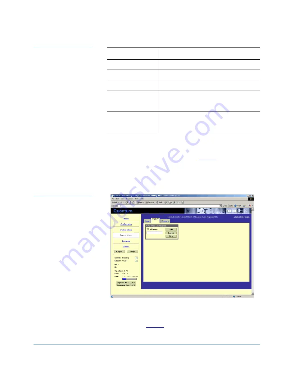
 in the Trap Destination area (see 

figure 68

), to set the IP 

addresses that are to receive the traps generated by the 

DX-Series 

system,

 for example, 

12.34.56.78

. Up to five trap destination addresses 

may be set. If less than five trap destinations are required, leave unused 

Trap Destination

 fields blank.

Figure 68  SNMP Trap 
Destinations

6

Click 

Add

 to add the IP address to the trap destinations and return to the 

SNMP tab.

7

Click 

New

 in the Community Management area to edit the SNMP 

communities (see 

figure 69

).

Field

Description

Informational

If selected, 

Informational Traps 

are enabled.

Warning

If selected, 

Warning Traps

 are enabled.

Failure

If selected, 

Failure Traps

 are enabled.

Available

If selected, a trap is generated every time the 

library transitions from an unavailable to an 

available state.

Unavailable

If selected, a trap is generated every time the 

library transitions from an available to an 

unavailable state.

Summary of Contents for DX100

Page 1: ...Unpacking the DX Series System 7 Installing the DX Series System 12 Locating the Mounting Position 12 Installing the DX Series Storage Array 15 Installing the Fibre Channel Switch DX100 Only 20 Instal...

Page 2: ...apacity on Demand CoD Crosslink Mechanism DLT DLTSage DLTtape Super DLTtape Performance on Demand PoD PRISM PRISM Storage Architecture logo SiteCare StackLink StorageCare SuperLoader and ValueLoader a...

Page 3: ...ual RAID controllers and the overall DX100 system can expand to sixteen storage arrays The DX100 controller also has a full compliment of Fibre Channel HBAs two quad port HBAs and four dual port HBAs...

Page 4: ...ure 1 DX Series Components Selecting an Installation Location 0 When choosing an installation site for the DX Series system consider the following requirements Rack Space Requirements Environmental Co...

Page 5: ...15U with a maximum of 4 storage arrays DX100 base unit 12U 58U for a maximum of 16 storage arrays two Fibre Channel switches two or more AC power sequencers and one Ethernet switch Weight Storage arr...

Page 6: ...e the following environmental conditions Humidity 20 80 non condensing Temperature 15 C 35 C 59 F 95 F Altitude 984 to 10 000 feet 300 to 3048 meters These environmental conditions apply when the DX S...

Page 7: ...avoid damaging these parts while performing installation procedures always observe the following precautions Keep the DX Series system turned off during all installation procedures Use an antistatic...

Page 8: ...als see figure 3 figure 4 figure 5 and figure 6 DX Series controller DX Series storage array s DX Series Fibre Channel switch DX100 only Ethernet switch DX100 only AC power sequencer DX100 only Compon...

Page 9: ...06 Unpacking the DX Series System 9 Figure 3 Unpacking the DX30 Bottom Storage array Cover DX30 packaging Storage array accessory kit Antistatic bag Hard drive Controller Controller accessory kit Anti...

Page 10: ...es System Figure 4 Unpacking the DX100 Top packing foam Storage array Cover DX100 packaging Storage array accessory kit Antistatic bag Hard drive Top Controller Controller accessory kit Antistatic bag...

Page 11: ...Series System 11 Figure 5 Unpacking Additional Storage Array s Figure 6 Unpacking the Power Kit Storage array Storage array accessory kit Antistatic bag Hard drive sleds Bottom packing foam Top packin...

Page 12: ...Both components of the DX Series system are designed to fit in a standard 19 inch wide rack It is important to the chassis installation to locate the hole pattern in the rack rails see figure 7 The ch...

Page 13: ...g the DX Series components from the bottom of the rack 2 or more AC power sequencers 1U 1U per pair DX100 only Additional DX Series array module 3U 3U 1U 1 75 in 44 45mm 14U of rack space 1U 1 75 in 4...

Page 14: ...2 06 A01 October 2006 14 Installing the DX Series System Figure 8 Mounting Locations DX Series controller 3U Ethernet switch Fibre Channel Switch Storage arrays 1U DX100 only 1U DX100 only 8 shown 3U...

Page 15: ...ing the Storage Array Table 3 Storage Array Mounting Hardware Note If this is an upgrade to an existing DX Series system see Installing Additional Storage Arrays on page 41 Qty Figure Description 6 32...

Page 16: ...gure 9 Figure 9 Installing the Mounting Spacers Installing the Storage Array 0 1 Install the left and right storage array support brackets at the beginning of a hole pattern see Locating the Mounting...

Page 17: ...e storage array mounting holes if necessary Refer to table 2 to determine the type of hardware required for your rack see figure 11 for hole location Figure 11 Storage Array Mounting Holes 3 Tighten t...

Page 18: ...ray to the rack with two 10 32 x 1 25 in M5 x 32 metric also provided black PHILLIPS screws on each side of the front of the chassis see figure 12 Figure 12 Securing the Storage Array to the Rack 7 In...

Page 19: ...ckets 8 Install each of the hard drive sleds into the DX Series storage array chassis see figure 14 Note The hard drives must be installed in the proper sequence since RAID sets have already been esta...

Page 20: ...nstallation continue with Installing the Fibre Channel Switch DX100 Only Installing the Fibre Channel Switch DX100 Only 0 To install the Fibre Channel switch refer to the Fiber Channel switch hardware...

Page 21: ...unting holes The back mounting bracket must be installed in the second hole see figure 15 Qty Figure Description 4 Mounting plates used only with rack rails with through holes or threaded holes 14 Slo...

Page 22: ...bling the Right and Left Support Brackets 2 Remove the right and left slide rails from the support brackets 3 Install the right and left slide rails on the Fibre Channel switch with three slotted scre...

Page 23: ...install the Fibre Channel switch support brackets with two PHILLIPS screws on each bracket in the front and in the back of the rack see figure 17 Note To support bracket installation in racks with th...

Page 24: ...A01 October 2006 24 Installing the DX Series System Figure 17 Installing the Right and Left Support Brackets in the Rack 5 Slide the Fibre Channel switch into the support brackets in the back of the...

Page 25: ...al Fibre Channel switch in a second rack to support more than 8 storage arrays Installing the Ethernet Switch DX100 Only 0 To install the Ethernet switch 1 Install the mounting ears on to the Ethernet...

Page 26: ...em Figure 19 Installing the Ethernet Mounting Ears 2 Install the Ethernet switch into the back of the rack directly above the Fibre Channel switch and secure with two screws on each side see figure 20...

Page 27: ...ler 1 Each DX Series controller rail is shipped in three pieces six total for both rails see figure 21 Figure 21 DX Series Controller Rails 2 Install the chassis mounting plate on each side of the con...

Page 28: ...ocking plate at the appropriate depth see figure 23 Figure 23 Assembling the Controller Rails 4 Install the DX Series controller rails into the rack with four 10 32 x 50 in PHILLIPS screws on each sid...

Page 29: ...the DX Series System 29 Figure 24 Installing the DX Series Controller Rails 5 Slide the DX Series controller into the support brackets in the rack and secure with two black 10 32 x 75 in PHILLIPS scr...

Page 30: ...he correct order Installing the AC power sequencers consists of the following steps Configuring the AC Power Sequencer Cabling and Installing the AC Power Sequencer Configuring the AC Power Sequencer...

Page 31: ...31 Figure 26 Setting the Power Sequencer Strapping IDs 2 Remove the three PHILLIPS screws securing the mounting brackets on each side of the power sequencer see figure 27 Figure 27 Removing the Mount...

Page 32: ...bly Cabling and Installing the AC Power Sequencer 0 To simplify installation the power cords for the AC power sequencer controller Ethernet switch Fibre Channel switch and storage arrays must be insta...

Page 33: ...two pan head PHILLIPS screws provided in the accessory kit see figure 30 Figure 30 Installing the Cable Clamp and Power Cable 3 Install the AC power cable through the cable clamp and into the AC power...

Page 34: ...4 Connect the first power connector on the controller to outlet J1 on the first AC power sequencer and secure with a tie wrap see figure 32 Figure 32 Connecting the First Power Connector 5 Connect th...

Page 35: ...Storage array 2 first connector Storage array 3 first connector Storage array 4 first connector Sequencer 2 Secondary AC Controller FC switch 1 Storage array 1 second connector Storage array 2 second...

Page 36: ...roller Ethernet and Fibre Channel Switch Note Odd and even numbered AC power sequencers should be on separate circuits for redundancy Note The storage arrays MUST be connected to the exact outlets spe...

Page 37: ...J6 J5 J4 J3 J2 J1 AC input in out Second AC power sequencer CAT5 cable Storage array 3 Storage array 1 Storage array 2 Primary AC power source Secondary AC power source separate circuit separate circ...

Page 38: ...r source on a dedicated circuit Ensure that the AC inputs are secured to the power sequencers with cable retention clamps J8 J7 J6 J5 J4 J3 J2 J1 AC input 2nd Fibre in out J8 J7 J6 J5 J4 J3 J2 J1 AC i...

Page 39: ...input in out Sixth AC power sequencer CAT5 cable Storage array 11 Storage array 9 Storage array 10 Primary AC power source Secondary AC power source separate circuit separate circuit To the Out port...

Page 40: ...rs for thirteen to sixteen storage arrays The first third fifth and seventh AC power sequencers are installed in the front of the rack and the second fourth sixth and eight AC power sequencers are ins...

Page 41: ...switch and the storage array s need SFP Small Form Factor Pluggable connectors installed prior to connecting Fibre Channel cables The SFP connectors are located in both the Fibre Channel switch and s...

Page 42: ...y Figure 40 Installing the SFPs in the Fibre Channel Switch DX100 Only Figure 41 Installing the SFP s in the Connection Modules 0 7 2 3934 4 0 5 4 5 4 28 4 Required SFP for controller connection Requi...

Page 43: ...Storage Array Dip Switches 0 Each storage array has a set of dip switches located on the back of the array in the upper left hand corner The switches are set in manufacturing but verify the settings p...

Page 44: ...rage array 2 FC CH0 right hand port FC port 3 Storage array 3 FC CH0 right hand port FC port 4 Storage array 4 FC CH0 right hand port FC port 5 Customer FC host FC port 6 Additional FC host Eth0 Custo...

Page 45: ...Fibre Channel host s connectors AC Power connectors AC Power connectors AC Power connectors Customer network Dual port Fibre Channel HBA Quad port Fibre Channel HBA Controller Storage array 1 Storage...

Page 46: ...ntroller Connections see figure 44 FC Switch Network FC port 1 FC Switch 1 port 1 FC port 2 FC Switch 2 port 1 9 to 16 arrays only FC port 3 FC Switch 2 port 11 9 to 16 arrays only FC port 4 FC Switch...

Page 47: ...ction module FC Ch0 right hand port FC switch 1 port 7 Secondary connection module FC Ch1 left hand port FC switch 1 port 17 Storage array 3 Primary connection module FC Ch0 right hand port FC switch...

Page 48: ...ule FC Ch1 left hand port FC switch 2 port 17 Storage array 11 Primary connection module FC Ch0 right hand port FC switch 2 port 3 Secondary connection module FC Ch1 left hand port FC switch 2 port 13...

Page 49: ...structions Document 6513502 06 A01 October 2006 Cabling the DX Series System 49 Storage array 16 Primary connection module FC Ch0 right hand port FC switch 2 port 10 Secondary connection module FC Ch1...

Page 50: ...ibre Channel host s 1 2 7 6 5 4 3 12 11 10 9 8 13 14 15 16 17 18 19 20 1 2 3 4 Eth0 Eth1 13 14 15 16 Customer network Controller First Fibre Channel switch Storage array 1 Storage array 2 Storage arra...

Page 51: ...ibre Channel host s 1 2 7 6 5 4 3 12 11 10 9 8 13 14 15 16 17 18 19 20 1 2 3 4 Eth0 Eth1 13 14 15 16 Customer network Controller First Fibre Channel switch Storage array 5 Storage array 6 Storage arra...

Page 52: ...ibre Channel host s 1 2 7 6 5 4 3 12 11 10 9 8 13 14 15 16 17 18 19 20 1 2 3 4 Eth0 Eth1 13 14 15 16 Customer network Controller Second Fibre Channel switch Storage array 9 Storage array 10 Storage ar...

Page 53: ...ibre Channel host s 1 2 7 6 5 4 3 12 11 10 9 8 13 14 15 16 17 18 19 20 1 2 3 4 Eth0 Eth1 13 14 15 16 Customer network Controller Second Fibre Channel switch Storage array 13 Storage array 14 Storage a...

Page 54: ...r to the system Two AC power sequencer are required for one to four storage arrays Four AC power sequencers are required for five to eight storage arrays Six AC power sequencers are required for nine...

Page 55: ...e following section to turn on the DX Series system Turning on the DX30 Turning on the DX100 Turning on the DX30 0 The DX30 components must be turned on in the following order DX Series storage array...

Page 56: ...hat the array is starting up When all tests are completed the LCD will display Quantum DX and Ready see figure 49 Figure 49 Storage Array LCD Display 2 Turn the DX Series controller on by pushing the...

Page 57: ...nfiguring the DX Series consists of the following steps Connecting to the DX Series Controller Configure Service Options Configuring User Options Creating Cartridges Updating Device Firmware Running t...

Page 58: ...ce PC see figure 51 Figure 51 Connecting the Service PC to the DX Series Controller 2 Open a HyperTerminal window on the service PC and set the following properties Baud rate 115200 Data bits 8 Parity...

Page 59: ...ber of licensed storage arrays 6 Enter the number of licensed storage arrays and press Enter The system prompts you to confirm the service options 7 Type y and press Enter to accept the service option...

Page 60: ...st create tape cartridges on the storage array s To create cartridges on the storage array s 1 Select 5 from the Service Menu see figure 52 to create cartridges 2 The system warns you that creating ca...

Page 61: ...t in capacity If you select 80 tape cartridges each cartridge has 20 GB capacity b If you select By capacity you choose between 20 and 1700 GB 43 and 1450 for second RAID set capacity per cartridge Th...

Page 62: ...r example if you select 1 tape cartridge per RAID set each cartridge has approximately 1 7 TB 1 45 TB for the second RAID set in capacity If you select 80 tape cartridges each cartridge has 20 GB capa...

Page 63: ...re updates Do you wish to update y n Type Y and press Enter to update the storage array firmware After the storage arrays are updated the update process continues hard drive s require updates Do you w...

Page 64: ...ler 0 Accessing the DX Series controller consists of the following steps Setting Up the Service PC Connecting the Service PC to the Network Setting Up the Service PC 0 To setup the service laptop to c...

Page 65: ...The Log In screen displays see figure 53 Figure 53 Log In Screen Note You can also directly connect the service PC to Eth0 on the DX Series controller using a cross over cable Note If Internet Explor...

Page 66: ...Login The License page displays see figure 54 Figure 54 License Page 6 After the customer has read and agreed to the license agreement press I Accept The Registration page displays see figure 55 Note...

Page 67: ...he DX Series system to be easily serviced and maintained If you do not want to register on line press Skip then fill out and mail the warranty card included in the DX Series accessory kit The Home pag...

Page 68: ...on must be created on the DX Series system Up to eight partitions can be added to a DX30 system and up to thirty two partitions can be added to a DX100 system To add a partition 1 Turn the DX Series s...

Page 69: ...LT7000 available to the host and backup application in this partition The Default partition contains 6 tape drives at the time of installation however you can change the number of drives DX30 up to 30...

Page 70: ...es system to the online state from the Utilities page The partition is added to the partition list To add another partition repeat this procedure Configuring the Network Information 0 If you have not...

Page 71: ...be set from the DX Series web pages Setting the correct date and time allows the DX Series system to provide accurate reports when events occur Field Description Hostname View or set the hostname for...

Page 72: ...using the Change button for the system date and drop down boxes for the system time b Select Use NTP Network Time Protocol to synchronize the DX Series system clock to the U S Naval Observatory Maste...

Page 73: ...he DX Series system management pages but not change them The administrator user can both view and change the management pages This section allows you to change the passwords for these accounts To set...

Page 74: ...h a secure SSL connection your DX Series system must have an encryption key assigned to it by a Certification Authority in the form of a certificate file private key file and pass phrase Once you inst...

Page 75: ...your pass phrase and press Enter 8 A Successful Upload page displays indicating that the SSL certificate file has been installed on the system Click Ok to continue The certificate displays in the cert...

Page 76: ...scription Make the Node WWN While the Port WWNs are always unique the Node WWNs can be set according to the Make the Node WWN section as follows Selecting Globally Unique but same for all ports makes...

Page 77: ...ecific Fibre Channel port a Click Auto Populate to allow the DX Series controller to automatically assign virtual devices to a Fibre Channel port The controller assigns a robot and partition to each p...

Page 78: ...splays the Email tab see figure 66 Figure 66 Email Tab 3 Edit the Email server information as desired see table 12 for a description of the fields and click Apply 4 After editing the Email server info...

Page 79: ...as starting up or shutting down the system an email is sent to everyone on the operator access recipient list Message Type Soft Error When a soft error has occurred on the DX Series system such as an...

Page 80: ...messages called protocol data units PDUs to different parts of a network SNMP compliant devices called agents store data about themselves in Management Information Bases MIBs and return this data to...

Page 81: ...rap destinations are required leave unused Trap Destination fields blank Figure 68 SNMP Trap Destinations 6 Click Add to add the IP address to the trap destinations and return to the SNMP tab 7 Click...

Page 82: ...address edit box must also end in a zero c Subnet mask in the Network Mask field d Access rights for the new community Get allows SNMP get operations Get Set allows both SNMP get and put operations 9...

Page 83: ...the configuration information as desired and click Apply The Contacts tab details are shown in table 15 and table 16 Table 15 Company Information Field Description Company Name View or edit the compa...

Page 84: ...ontract number Field Description Name View or edit the primary secondary contact name Email Address View or edit the primary secondary contact email address Phone View or edit the primary secondary co...

Page 85: ...the DX Series Configuration File 0 This option allows the current configuration to be downloaded to the administrator s system as a single file The system configuration file contains all of the config...

Page 86: ...A confirmation message will display asking whether to open or save the file 4 Select Save this file to disk and click OK A Results page indicates the configuration file has been downloaded 5 Click OK...

Page 87: ...stallation Instructions Document 6513502 06 A01 October 2006 Configuring the DX Series System 87 Figure 73 Shutting Down the DX Series System 3 Under System Shutdown click Restart The DX Series reboot...

Page 88: ...Quantum DX Series System Unpacking and Installation Instructions Document 6513502 06 A01 October 2006 88 Configuring the DX Series System...

Reviews: