


7-68
Field
–
Replaceable Units (FRUs)
501510 Rev. S
CAUTION
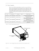
Only dual-redundant Power Supply Modules (P/N 510170-03-8) can be re-
placed while the RLS is powered on. Do not attempt to replace Power Supply
Modules (P/N 510170-01-2 or 510170-02-0) with power applied to the RLS.
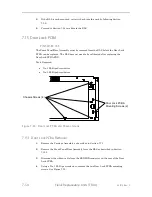
7.21.1
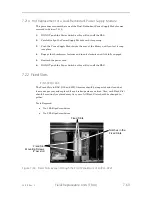
Removal of a Single Power Supply Module
1.
Push the Power Switch on the Front Panel/Door until its button is in the out position.
2.
Remove the power cord from the Power Supply Module.
3.
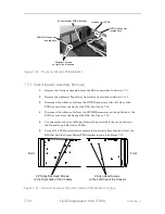
Turn the two thumbscrew fasteners counter-
clockwise until they’re fully dise
ngaged.
4.
Grasp the handle and gently pull the Power Supply Module out of the RLS.
7.21.2
Replacement of a Single Power Supply Module
This procedure assumes the Power Supply Module was removed in Section 7.21.1.
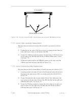
1.
Carefully align the Power Supply Module with its opening.
2.
Push the Power Supply Module into the rear of the library until you feel it
snap
into place.
3.
Engage the two thumbscrew fastener(s) and turn them clockwise until th
ey’re
fully engaged.
4.
Reattach the power cord.
5.
Push the Power Switch on the Front Panel/Door to restore power to the RLS.
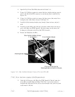
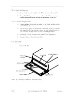
7.21.3
Hot Removal of a Dual-Redundant Power Supply Module
1.
DO NOT push the Power Switch as this will turn off the RLS.
2.
IDENTITY THE FAILED module! An alert on the LCD should indicate if the left
or right module failed. Remember that left and right are backwards when ad-
dressing the Power Supply Modules from the rear of the library. The failed mod-
ule’s LED will not be illuminated.
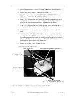
3.
Remove the power cord from the FAILED Power Supply Module.
4.
Turn the thumbscrew fastener counter-
clockwise until it’s fully dise
ngaged.
5.
Grasp the handle and gently pull the Power Supply Module backwards out of the
RLS.
Summary of Contents for RLS-4470
Page 1: ...RLS 8000 Tape Library Technical Service Manual 501510 Rev S...
Page 2: ......
Page 14: ...xiv 501510 Rev S This page left blank intentionally...
Page 16: ...1 2 Introduction 501510 Rev S Table 1 1 Applicable Documents...
Page 20: ...1 6 Introduction 501510 Rev S This page left blank intentionally...
Page 23: ...501510 Rev S Description and Theory of Operation 2 3...
Page 34: ......
Page 50: ...3 16 The Operator Interface 501510 Rev S This page left blank intentionally...
Page 64: ...4 14 The Maintenance Menu 501510 Rev S This page left blank intentionally...
Page 65: ...501510 Rev S The Private Menu 5 1 5 The Private Menu...
Page 69: ...501510 Rev S The Private Menu 5 5 10 Close the Front Panel Door...
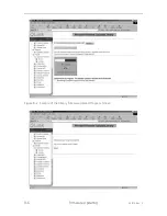
Page 188: ...8 10 Firmware Updating 501510 Rev S Figure 8 7 Properties Screen...
Page 205: ...501510 Rev S RLS Expansions 9 13 This page left blank intentionally...


