


501510 Rev. S
Field
–
Replaceable Units (FRUs)
7-63
2.
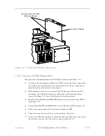
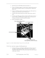
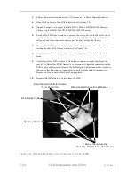
Carefully align the Channel mating connector on the DIA with its mate on the Drive
Bay PCBA Assembly. Slowly and gently push the DIA into the Drive Bay PCBA As-
sembly Channel connector. DO NOT FORCE this mating. If significant resistance is
met, pull the DIA off and check for bent pins on the Drive Bay PCBA Assembly. Re-
peat this step for each DIA that is being replaced/changed.
3.
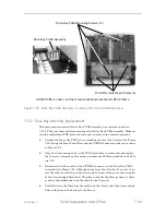
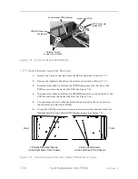
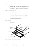
Position the retaining bracket on the library’s chassis, so that the t
hree screw
holes are aligned with the threaded holes of the chassis.
4.
Using a No. 2 Phillips screwdriver, replace the three flat-head screws that se-
cure the retaining bracket to the library. See Figure 7-40.
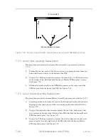
5.
Carefully align the threaded hole in each Drive Interface Adapter with the screw
holes in the retaining bracket.
6.
Using a No. 2 Phillips screwdriver, replace each of the Drive Interface Adapter
flat-head screws that secure the DIAs to the retaining bracket. See Figure 7-40.
7.
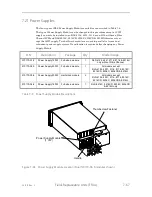
Follow the instructions in Section 7.21 to reinstall the Power Supply Module(s).
8.
Reconnect the SCSI cables to the Tape Drives (T1-T4) as they were originally
connected.
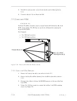
7.19
DFA (Direct Fibre Attach) Duplex Cable
RLS-8216CD/8236CD/8236D/
8204D/8244D/8404D/8444D
(LTO) P/N 510463-01-1
The RLS Power Supply Module(s) must be removed before a DFA Duplex Cable can
be replaced. No calibration is required after replacing a DFA Duplex Cable.
Tools Required: No. 2 Phillips Screwdriver
CAUTION
The DFA Duplex Cables are sensitive to bending so care must be taken when
handling the cables. Do not allow them to be bent, crimped or pinched dur-
ing the replacement process.
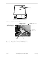
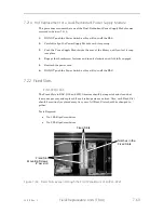
7.19.1
DFA Duplex Cable Removal
1.
Remove power from the RLS by first pressing the power switch off and then re-
moving the power cord (two power cords if dual-redundant power supply mod-
ules are installed).
2.
Disconnect all fibre cables from the Tape Drives (T1, T2, T3 & T4). Note how
they were connected so they can be reconnected in the same manner.
Summary of Contents for RLS-4470
Page 1: ...RLS 8000 Tape Library Technical Service Manual 501510 Rev S...
Page 2: ......
Page 14: ...xiv 501510 Rev S This page left blank intentionally...
Page 16: ...1 2 Introduction 501510 Rev S Table 1 1 Applicable Documents...
Page 20: ...1 6 Introduction 501510 Rev S This page left blank intentionally...
Page 23: ...501510 Rev S Description and Theory of Operation 2 3...
Page 34: ......
Page 50: ...3 16 The Operator Interface 501510 Rev S This page left blank intentionally...
Page 64: ...4 14 The Maintenance Menu 501510 Rev S This page left blank intentionally...
Page 65: ...501510 Rev S The Private Menu 5 1 5 The Private Menu...
Page 69: ...501510 Rev S The Private Menu 5 5 10 Close the Front Panel Door...
Page 188: ...8 10 Firmware Updating 501510 Rev S Figure 8 7 Properties Screen...
Page 205: ...501510 Rev S RLS Expansions 9 13 This page left blank intentionally...


