


501510 Rev. S
Field
–
Replaceable Units (FRUs)
7-55
5.
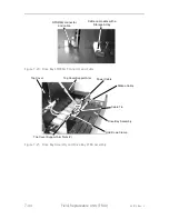
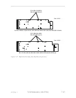
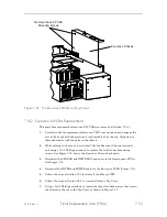
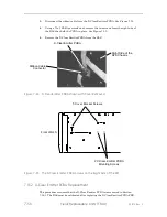
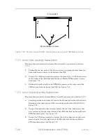
Using a No. 2 Phillips screwdriver, remove the four chassis screws to allow for
PCBA removal. See Figure 7-33.
6.
Carefully pull on the front, right side of the chassis to create enough space for
the PCBA to be removed.
7.
Carefully remove the Door Lock PCBA from the library.
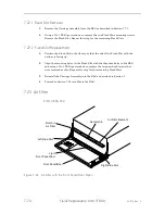
7.15.2
Door Lock PCBA Replacement
This procedure assumes that the Door Lock PCBA was removed in Section 7.15.1.
1.
Carefully pull on the front, right side of the chassis to create enough space for
the PCBA to be inserted.
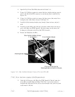
2.
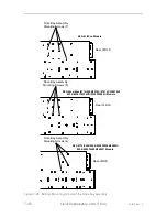
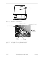
Insert the PCBA into the RLS with the SENSOR connector towards the top and
turn it so that the two mounting screw threaded inserts are aligned with the
screw holes in the front of the chassis. See Figure 7-33.
3.
Using a No. 1 Phillips screwdriver, reinstall the two door lock PCBA mounting
screws that were removed earlier. See Figure 7-33.
4.
Reconnect the ribbon cable to the SENSOR connector on the rear of the PCBA.
5.
Using a No. 2 Phillips screwdriver, reinstall the four chassis screws that were
removed earlier. See Figure 7-33.
6.
Reinstall the Front Panel/Door Assembly onto the RLS as described in Section
7.10.2.
7.
Reinstall the Carriage Assembly as described in Section 7.
7.16
X-Clear Emitter PCBA
P/N 501597-01-7
The Carriage Assembly must be removed from the RLS before the X-Clear Emitter
PCBA can be replaced.
Tools Required:
•
No. 1 Phillips Screwdriver
•
No. 2 Phillips Screwdriver
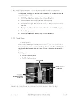
7.16.1
X-Clear Emitter PCBA Removal
1.
Remove the Carriage Assembly from the RLS (Section 7.7.1).
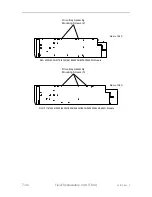
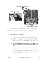
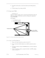
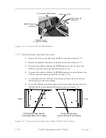
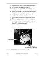
2.
Using a No. 2 Phillips screwdriver, remove the five screws from the right side of
the RLS that hold the Cover Bracket in place. Remove the cover and set it aside.
See Figure 7-35.
Summary of Contents for RLS-4470
Page 1: ...RLS 8000 Tape Library Technical Service Manual 501510 Rev S...
Page 2: ......
Page 14: ...xiv 501510 Rev S This page left blank intentionally...
Page 16: ...1 2 Introduction 501510 Rev S Table 1 1 Applicable Documents...
Page 20: ...1 6 Introduction 501510 Rev S This page left blank intentionally...
Page 23: ...501510 Rev S Description and Theory of Operation 2 3...
Page 34: ......
Page 50: ...3 16 The Operator Interface 501510 Rev S This page left blank intentionally...
Page 64: ...4 14 The Maintenance Menu 501510 Rev S This page left blank intentionally...
Page 65: ...501510 Rev S The Private Menu 5 1 5 The Private Menu...
Page 69: ...501510 Rev S The Private Menu 5 5 10 Close the Front Panel Door...
Page 188: ...8 10 Firmware Updating 501510 Rev S Figure 8 7 Properties Screen...
Page 205: ...501510 Rev S RLS Expansions 9 13 This page left blank intentionally...