501510 Rev. S
The Operator Interface
3-7
3.3.7
The Status LEDs
The three status LEDs display the current operational status of only the RLS Medi-
um-changer. Only one of them is illuminated at a time and they have the following
significance:
NAME
COLOR
INDICATION
READY
GREEN
The RLS is ready to accept commands
BUSY
AMBER
The RLS is busy executing a command
FAULT
RED
A fault has occurred and the RLS cannot accept commands
Table 3-1 Status LEDs Descriptions
3.4
The Top Menu
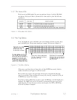
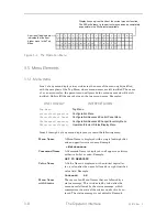
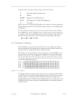
To see the Top Menu, turn on the RLS, wait until it displays the date and time, then
press the MENU key. The operator should see a display like the one in Figure 3-3.
A dot in front of an item indicates a
sub-menu. To go to the sub-menu,
press the ENTER key.
DOWN and UP arrows indicate
additional lines are to be seen by
scrolling the display with the UP
and DOWN key.
Display line one always
indicates the title (or its
abbreviation) of the
current menu or function.
The
item pointer
to the left of an
item indicates which item will be
acted upon when the ENTER key
is pressed. For example, press
ENTER when the arrow points to
Configuration and the display will
change to the Configuration menu.
Figure 3-3 Top Menu Display
If the arrow is positioned next to Operation and then ENTER is pressed, a display
similar to that shown in Figure 3-4 will be observed.
The up and down arrows at the right edge of the display indicate that additional
choices are available. These additional choices can be viewed by using the (UP) and
(DOWN) keys to scroll the display.
To go back to the Top Menu from any point, press the EXIT key until the Top Menu is
displayed. The MENU key can also be pressed to accomplish the same result with a
single keystroke. To leave the menu system entirely, press the EXIT or MENU key
while the Top Menu is displayed.
Summary of Contents for RLS-4470
Page 1: ...RLS 8000 Tape Library Technical Service Manual 501510 Rev S...
Page 2: ......
Page 14: ...xiv 501510 Rev S This page left blank intentionally...
Page 16: ...1 2 Introduction 501510 Rev S Table 1 1 Applicable Documents...
Page 20: ...1 6 Introduction 501510 Rev S This page left blank intentionally...
Page 23: ...501510 Rev S Description and Theory of Operation 2 3...
Page 34: ......
Page 50: ...3 16 The Operator Interface 501510 Rev S This page left blank intentionally...
Page 64: ...4 14 The Maintenance Menu 501510 Rev S This page left blank intentionally...
Page 65: ...501510 Rev S The Private Menu 5 1 5 The Private Menu...
Page 69: ...501510 Rev S The Private Menu 5 5 10 Close the Front Panel Door...
Page 188: ...8 10 Firmware Updating 501510 Rev S Figure 8 7 Properties Screen...
Page 205: ...501510 Rev S RLS Expansions 9 13 This page left blank intentionally...


