background image


8-12 

Firmware Updating 

501510 Rev. S


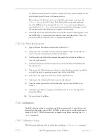
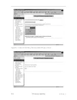
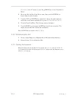
Figure 8-9   Settings Screen Under the Properties Menu 

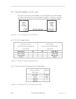
You may also consider 

ASCII Setup

 parameters to satisfy your display require-

ments. 


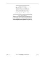
Figure 8-10   ASCII Setup Screen under Settings Screen 

Summary of Contents for RLS-4470

Page 1: ...RLS 8000 Tape Library Technical Service Manual 501510 Rev S...

Page 2: ......

Page 3: ...as needed for these uses Reproduction in whole or in part for any other use or by any other party is prohibited without prior written per mission from Qualstar Corporation Every effort has been made...

Page 4: ...ser will be required to correct the interference at his own expense Shielded cables are required for this device to comply with FCC Rules Use shielded cables when connecting this device to others Euro...

Page 5: ...ods Aluminum Door exterior panels frame robotics Stainless steel Robot guides Steel Some frames fasteners Plastic Window cartridge magazines tape cassettes Copper Internal wiring motors SCSI cables Pa...

Page 6: ...ead based solder exemption until such time as industry data verifies that lead free solders are capable of meeting or ex ceeding the documented reliability and quality standards achieved with lead bas...

Page 7: ...2 3 2 Handler 2 12 2 3 3 Field Replaceable Units FRUs 2 13 3 The Operator Interface 3 1 3 1 The Door Lock 3 1 3 2 Using the Menu System 3 1 3 2 1 The MENU Control Key 3 2 3 2 2 The UP and DOWN Control...

Page 8: ...ging General Description 4 9 4 9 The Maintenance Log Display Entry menu 4 10 4 10 The Maintenance Test Inventory menu 4 11 4 11 The Maintenance Test Keyboard status screen 4 11 4 12 The Maintenance Te...

Page 9: ...1 2 When the power is turned on no motion occurs the LCD does not illuminate the 24V LED on the IPM rear of RLS blinks 6 1 6 1 3 When the power is turned on the LCD is illuminated and shows the librar...

Page 10: ...o Target Drive 6 8 6 4 4 Target Full 6 8 6 4 5 Source Empty 6 8 6 4 6 No Source Magazine 6 8 6 4 7 No Source Drive 6 9 6 4 8 Tape Not Ejected 6 9 6 4 9 The Door is Locked 6 9 6 4 10 The Door is Open 6...

Page 11: ...sembly Removal 7 35 7 11 2 Tape Drive Assembly Replacement 7 35 7 11 3 Verifying a Tape Drive Assembly Installation 7 37 7 11 4 Drive Fillers 7 37 7 12 Serial Control Panel PCBA 7 38 7 12 1 Serial Con...

Page 12: ...pply Module 7 69 7 22 Fixed Slots 7 69 7 22 1 Fixed Slot Removal 7 70 7 22 2 Fixed Slot Replacement 7 70 7 23 Air Filter 7 70 7 23 1 Air Filter Inspection 7 71 7 23 2 Air Filter Replacement 7 72 7 24...

Page 13: ...A Chassis Storage Array Expansion Kit Installation 9 6 9 2 4 Style B Chassis Storage Array Removal 9 7 9 2 5 Style B Chassis Storage Array Expansion Kit Installation 9 9 9 2 6 Entering the Update Pas...

Page 14: ...xiv 501510 Rev S This page left blank intentionally...

Page 15: ...ctions For information about the SCSI interface or other information outside the scope of this manual please refer to the appropriate documents listed below Subject Document Qualstar Documen t Number...

Page 16: ...1 2 Introduction 501510 Rev S Table 1 1 Applicable Documents...

Page 17: ...nstallation and Operation Manual 1 2 Important Safety Information All of the operating instructions and maintenance procedures in Qualstar manuals must be followed to prevent personal injury or damage...

Page 18: ...OR CORPORATION DS1225AB OR A SGS THOMPSON MICROELECTRONICS M48258X IC ON THE EXECUTIVE PCBA CONTAINS AN INTEGRAL LITHIUM BATTERY AN EXPLOSION DANGER EXISTS IF THE IC IS INCORRECTLY REPLACED REPLACE TH...

Page 19: ...501510 Rev S Introduction 1 5 HERSTELLER ANGABE ERSETZT WERDEN DIE ENTSORGUNG DES ALTEN IC S DARF NUR GEMAESS HERSTELLERANGABEN ERFOLGEN...

Page 20: ...1 6 Introduction 501510 Rev S This page left blank intentionally...

Page 21: ...nality Module IPM N A Standard Standard Standard 2 GB Fibre Channel Interface IPM N A Optional Optional Optional Q Link Remote Manager Standard Standard Standard Standard Quick swap tape drive carrier...

Page 22: ...D Tape Technology LTO LTO LTO LTO LTO HH LTO LTO Maximum No of Drives 1 2 2 2 2 2 2 Total Cartridge Capacity 1 12 36 12 44 12 44 16 36 36 Number of Magazines 16 3 9 3 11 3 11 4 9 9 Cartridges per Maga...

Page 23: ...501510 Rev S Description and Theory of Operation 2 3...

Page 24: ...e Capacity 44 44 44 44 12 44 12 44 Number of Magazines 11 11 11 11 3 11 11 Cartridges per Magazine 4 4 4 4 4 4 Barcode Reader Optional Optional Standard Standard Optional Standard LVD SE SCSI Interfac...

Page 25: ...22 2 cm 10 0 25 4 cm 8 0 20 3 cm Dual Redundant Hot Swappable Power Supply Option 7 1 8 cm A B 16 6 42 2 cm 2 0 5 1 cm C Rail Spacing Model A Dimension B Dimension 5116 XXX4 36 9 93 7 cm 34 9 88 6 cm...

Page 26: ...models that utilize AIT LTO SDLT and SAIT tape tech nology All units operate on internationally available AC power Brushless motors are used exclusively All digital closed loop servo systems use magn...

Page 27: ...powered by brushless DC motors turning precision lead screws and drive shafts Magnetic sensors provide position and velocity feedback to the motors while optical sensors provide absolute positional in...

Page 28: ...te through the Carriage PCBA the Interconnect PCBA and finally to the Executive PCBA These sensors provide continuous incremental posi tion feedback so the library always knows where its carriage is Z...

Page 29: ...th are operated by the Sensor Master PCBA The principle function is to detect an object unexpectedly obstructing the no man s land between the carriage and the cartridges It is also used to detect the...

Page 30: ...the changer s non volatile RAM the internal inventory data base and is available to the host computer upon request 2 2 4 Barcode Labels Pre printed barcode labels which are both human and machine read...

Page 31: ...ules Rack Mount Slide Kit The theory of operation is basically the same for all models regardless of which hardware configuration is used 2 3 1 RLS Models Figure 2 3 and Figure 2 4 show the location o...

Page 32: ...ge Magazines Handler Carriage Assembly Carriage Tape Drives Bezel Front Panel Door Assembly VIOP Door Figure 2 4 RLS as seen from the front 2 3 2 Handler Figure 2 5 shows the major components of the R...

Page 33: ...le separately as Field Replaceable Units FRUs Sometimes referred to as spare parts These components can be re moved and replaced in the field by qualified personnel See Chapter 7 for a complete list o...

Page 34: ......

Page 35: ...oor Lock Positions 3 2 Using the Menu System The Control Panel shown in Figure 3 2 allows a qualified individual to make configu ration changes to the RLS and to perform diagnostics This chapter expla...

Page 36: ...ntrol Keys While navigating through the menu system the UP and DOWN keys move the item pointer right pointing arrow up and down the left column of the display The display automatically scrolls when ne...

Page 37: ...aracter of the field by superimposing a flashing cursor over it This in dicates the Edit mode is active and the value of the highlighted character can now be changed using the UP and DOWN keys In the...

Page 38: ...rently in that it contains only commands and dismisses itself after executing one of its commands Simply point to one of the Quick Operation commands and press the ENTER key to invoke the command and...

Page 39: ...oval command from a host computer The OPEN VIOP command only appears in the menu when a Variable VIOP has been configured If the RLS has been configured for more than one logical library then the comm...

Page 40: ...mmand unlocks the Front Panel Door and allows the user to remove or install any number of cartridges in the magazine or fixed slots RLS 4124 and 4221 only The entire magazine may also be removed or re...

Page 41: ...ing the display with the UP and DOWN key Display line one always indicates the title or its abbreviation of the current menu or function The item pointer to the left of an item indicates which item wi...

Page 42: ...n Configuration Menu CA Control Panel Configuration Advanced Control Panel Menu CA Changer Inventory Configuration Advanced Changer Inventory Menu OES Display Operation Element Status Display Menu Lin...

Page 43: ...ee types of numeric values found within the system Unsigned Decimal Values Examples 23 07 123 Signed Decimal Values These values are always indicated by the presence of a plus or minus sign in front o...

Page 44: ...IZ MA MZ T 1 5 Table 3 2 The physical Location Field Character Definition Space This character is always a lower case p when describing the physical space Characters a d indicates logical libraries a...

Page 45: ...value and the DOWN key to select the previous value then press EXIT when done The list of choices wraps around so the operator can see all the choices by using just the UP or DOWN key 3 5 4 2 Editing...

Page 46: ...shown in the table starting with the space character followed by the A character and ending with the character The hex equivalents are those values sent over the SCSI interface in response to SCSI com...

Page 47: ...ystem is divided into three menus Configuration Mainte nance and Operation Each of these menus contains several sub menus Some of the sub menus may also contain more sub menus beneath them The Top Men...

Page 48: ...press the DOWN key until the arrow on the left side of the dis play points to the Display Revisions sub menu Press the ENTER key to view the Date Part Number Revision and Checksum of the RLS operating...

Page 49: ...ms only appear if all the required conditions for the menu have been configured and satisfied For example the Clean Drive menu only appears when all conditions are correct Additionally the Operation S...

Page 50: ...3 16 The Operator Interface 501510 Rev S This page left blank intentionally...

Page 51: ...the functionality of the liquid crystal display and menu control keys The Maintenance menu is available to the system user and is considered safe The user cannot break anything by using or misusing th...

Page 52: ...Figure 4 2 Maintenance Menu Part 2 NOTE The menus in this chapter reflect revision 0 122 of the operating firmware If an earlier revision of the firmware is being used some menu items may not appear i...

Page 53: ...the RLS which corresponds to the serial number printed on the nameplate label located on the rear of the unit 4 2 The Maintenance Display Prevents status screen M Display Prevents Initiator 0 Initiato...

Page 54: ...nt firmware 4 4 The Maintenance Display Stats status screen M Display Stats Aborts dddddddddd DoorOpn dddddddddd Filter dddddddddd Grips dddddddddd Minutes dddddddddd Moves dddddddddd Picks dddddddddd...

Page 55: ...a cartridge has been placed into a drive or storage location PowerOn This value is the number of times that the power has been turned on Resets This value is the number of Executive CPU resets includi...

Page 56: ...Id ddd FW Rev aaaa Loader Rev aaaaa Prod Id aaaaaa S N aaaaaa 3 3V ddd 5V ddd 2 5V ddd Air Temp C ddd CPU Temp C ddd UPDATE The Fibre Channel Info status screen displays the Fibre Channel IPM s config...

Page 57: ...gulator output 2 5V This value displays the 2 5V regulator output Air Temp This value displays the board s temperature in degrees Celsius CPU Temp This value displays the CPU s temperature in degrees...

Page 58: ...ar document number 501500 This menu determines which of the logged items are to be displayed If an item is set ON any of its logged data will be displayed If an item is set OFF it will not be displaye...

Page 59: ...tegories of information get logged Since the data log memory size is fixed turning off unwanted data categories frees up log memory space for the data categories that the user wishes to log Refer to t...

Page 60: ...s displayed However the system does track the number of events that would have been logged while the Entry menu was displayed and then adds that number as a log entry when the user exits the Entry men...

Page 61: ...the Maintenance Log menu 2 Press the EXIT key twice to return to the Maintenance Log menu 4 10 The Maintenance Test Inventory menu M Test Inventory Cartridges ddddd Labels ddddd CLEAR START STOP The T...

Page 62: ...out releasing the first key the blinking asterisk appears next to the second key s abbreviation as mentioned above Then if the first key is released its abbreviation and the blinking asterisk both dis...

Page 63: ...isplay screen use either the UP or DOWN key to select any one of the three test screens The first two test screens display the character set used by the RLS The third test screen checks the operation...

Page 64: ...4 14 The Maintenance Menu 501510 Rev S This page left blank intentionally...

Page 65: ...501510 Rev S The Private Menu 5 1 5 The Private Menu...

Page 66: ...5 2 The Private Menu 501510 Rev S Figure 5 1 The Private Menu Part 1 Figure 5 2 The Private Menu Part 2 Continued in Figure 5 2 Continued from Figure 5 1...

Page 67: ...configuration against unauthorized or unintentional changes and unauthorized manual operations Therefore the Master security lock must be disabled before a password can be set in the Private menu 5 2...

Page 68: ...structions below which assume that all RLS security locks are set to ON to disable the Master security lock 1 Open the Front Panel Door to disable the Door lock 2 Press the MENU key to display the Top...

Page 69: ...501510 Rev S The Private Menu 5 5 10 Close the Front Panel Door...

Page 70: ...personnel to access certain Private menu items while servicing the RLS Please note that only the first letter is capitalized Update is the password used by qualified service personnel to access oth er...

Page 71: ...splay Sense Display Stats Display Voltage Test Inventory Test Keyboard Test LC Display 5 Use the DOWN key to move the pointer to Test LC Display 6 Press the ENTER key to enter the Maintenance Test LC...

Page 72: ...SCSI BUS Sensor NOTE If a MASTER SECURITY message appears instead of a flashing cursor in step 11 above follow the instructions in Section 5 2 3 to disable the Master Security Lock then repeat this se...

Page 73: ...Section 5 3 3 disappears from the Private menu 1 Press the MENU key to open the Top Menu 2 Use the DOWN key to move the pointer to Private 3 Press the ENTER key to enter the Private menu Private Acce...

Page 74: ...ust first unlock the security locks before proceeding Use the procedure in section 5 2 to enter the Security menu and disable the Master Security Lock The user can also disable the Inventory Lock whil...

Page 75: ...checked against acceptance range parameters Each position or optical output reading must fall within its acceptable range before subse quent positions and thresholds are determined CAUTION If the RLS...

Page 76: ...command forces a BUS RESET command on the SCSI bus It may be used with caution to solve system development problems However using this command could prove quite disruptive on a live system CAUTION Ex...

Page 77: ...encounters some particularly dif ficult Handler problem it may become necessary to relay the data on this screen to a Qualstar Technical Support technician The Calibrated value and the Valid value ind...

Page 78: ...1 Demonstrations NOTE This item is locked by both the Master Security Lock and the Configuration Lock This menu allows for the Operation Demonstrations menu to be hidden YES The Operation Demonstrati...

Page 79: ...el Display menu If either of these methods is used and the operator then executes the Configuration menu s SET TO DEFAULTS command the custom text data is lost and the system s default text Qualstar R...

Page 80: ...justing the values in this menu can help to reduce some of the problems as sociated with inflexible host software Both decimal values are editable P Configuration SCSI PostPlaceDly ddddd PrePickRetrie...

Page 81: ...es are possible Boot occurs during firmware uploading 5V The 5V supply voltage to the Serial Control Panel Door Latch A zero indicates the Door is unlatched A 1 indicates the door is latched Temperatu...

Page 82: ...lll Source Valid FALSE Type DRIVE The Private Display Locations menu contains data from the library s inter nal inventory database The data in this menu differs from the data found in the Op eration E...

Page 83: ...indicates the prior location of the cartridge that is cur rently at the selected location The Item value is an internal number Source Valid TRUE FALSE A TRUE value means the Source Location data for...

Page 84: ...t takes for the Hall Effect sensors in the Z Axis brushless DC motor to move be tween two points The maximum value of 65 535 will be shown when the motor is not moving 5 4 13 The Private DriveBay stat...

Page 85: ...upply voltage to the Drive Bay 5V Low The lower limit of acceptable 5V supply voltage to the Drive Bay 5V High The upper limit of acceptable 5V supply voltage to the Drive Bay PsLeft Low High The low...

Page 86: ...re presently two types of DIA boards as shown in Table 5 4 below Type Purpose Functionality NONE N A A Tape Drive cannot be supported by this channel PASSIVE Hot Pluggable Tape Drives A drive may be c...

Page 87: ...Address The I2C address of the selected Drive Carrier microprocessor Type The part number of the Drive Carrier microprocessor s firmware Rev The revision of the Drive Carrier microprocessor s firmwar...

Page 88: ...ching regulators to operate Alarm This value is ON if the Inrush Limiter s output voltage is unacceptable Voltage The Inrush Limiter s output voltage Termination This value is ON if the RLS has comman...

Page 89: ...y Power Left or Right status screens display the sta tus of all power supply modules The right as viewed from the front of the RLS mod ule is only found on models with dual redundant power supply modu...

Page 90: ...module Ignore the LED value for FULLSIZE power supply modules Temperature The temperature in degrees Centigrade in the Left or Right power supply module Description Module P N Remarks FULLSIZE 125W 51...

Page 91: ...indicates the Carousel or Storage Array is moving Demand Edit this value to select a magazine to be moved to the front for access There is a one to one mapping of this numerical value to the alphabet...

Page 92: ...displays the present state of all the RLS sen sors as well as information about the model specific Sensor Master board SET TO DEFAULTS command This command will reset the threshold of the analog sens...

Page 93: ...aws are closed Magazine A value of 0 indicates a magazine is present at the current access position of the Carousel or Storage Array MagazineSlot 1 5 A value of 0 indicates a cartridge is present in t...

Page 94: ...5xxx 8xxx RLS 62xx 1 MagazineSlot1 MagazineSlot11 MagazineSlot11 2 MagazineSlot2 MagazineSlot02 MagazineSlot20 3 MagazineSlot3 MagazineSlot03 MagazineSlot34 4 MagazineSlot4 MagazineSlot34 N A 5 Magazi...

Page 95: ...r Supply Module remove power cord s first 3 Check the action of the Power Switch It should possess a definite latching feel at the end of its travel The sliding linkage on the right inside of the RLS...

Page 96: ...ode reader has failed 6 1 6 After Installing a Tape Drive it Fails to Appear in the Menu System 1 The drive carrier has failed to seat properly Using the lever remove the drive part way and reinsert i...

Page 97: ...see Section 7 6 and check that all the magazines and cartridges on the carousel are properly seated Verify the drive belt is in place and free of slack 6 2 6 Array Failed Array Jammed The Storage Arra...

Page 98: ...ck that the 10 conductor ribbon cable be tween the Interconnect and Drive Bay PCBAs is properly installed Go to the Pri vate Cabling menu to see if any cables are unplugged 6 2 11 No Carriage Found Du...

Page 99: ...501510 Rev S Troubleshooting 6 5 Check the cable between the Storage Array and the Drive Bay PCBAs Go to the Private Cabling menu to see if any cables are unplugged...

Page 100: ...Carousel Jammed The carousel mechanism failed to move successfully Check that there are no loose magazines or cartridges in the Carousel or Handler If there is a cartridge is in the Handler and it is...

Page 101: ...library 6 3 10 Left Fan Failed or Right Fan Failed The fan in the left or right Dual Redundant Power Supply Module is not turning at full speed If the fan is not obstructed by cable ties etc replace...

Page 102: ...ntermittently fail when all drives are simultaneously busy loading unloading or rewinding Replace the entire Power Supply Module The RLS must be powered down to accomplish this task 6 4 Operating Erro...

Page 103: ...only be done after certain upgrades and servicing In addition to these any of the POST Power On Self Test faults can hap pen during calibration 6 5 1 Calibration Fault A motion fault happened during c...

Page 104: ...the library is set up correctly for calibration and re try 6 5 6 Opto Cal Failed One or more of the optical sensors failed to calibrate properly Make sure the library is set up correctly for calibrat...

Page 105: ...o calibrate the RLS after changing a FRU The RLS can be commanded to calibrate itself automatically which takes approxi mately 5 minutes DANGER TO AVOID THE RISK OF PERSONAL INJURY TURN OFF ALL POWER...

Page 106: ...minimum touch an unpainted portion of the RLS chassis be fore handling any PCBAs NOTE Left and right sides of the RLS are referred to throughout this chapter Left and right are defined when viewing t...

Page 107: ...02 6 7 9 30 Yes Storage Array SDLT x 27 510172 02 6 7 9 30 Yes Storage Array SAIT x 44 LTO x 44 510172 03 4 7 9 30 Yes Front Panel Door Assembly Bezel 510179 01 3 7 10 30 No Front Panel Door Assembly...

Page 108: ...ly 4445 4470 8404 8444 501537 02 1 7 13 60 No Drive Bay PCBA Assembly 8236D 8204D 8244D 501957 01 3 7 13 60 No Drive Bay PCBA Assembly 5116 8116 501537 04 7 7 13 60 No Drive Bay PCBA Assembly 52 62 82...

Page 109: ...rt 7 7 Carriage Assembly with Barcode Reader Assembly 5116 8116 8216H Please contact technical support 7 7 Carriage Assembly with Barcode Reader Assembly 52 62 82xx 8404H 8444H Please contact technica...

Page 110: ...85 0 7 11 Tape Drive Assembly IBM LTO 5 SAS 501903 86 8 7 11 Tape Drive Assembly IBM LTO 5 SAS Ext 501903 87 6 7 11 Tape Drive Assembly IBM LTO 5 HH DFA 501903 88 4 7 11 Tape Drive Assembly IBM LTO 5...

Page 111: ...Open Ended Wrench Diagonal Cutters Long Nose Pliers Small Mirror optional Flashlight optional Table 7 3 Required Tools The materials listed in Table 7 4 are required when replacing the indicated FRUs...

Page 112: ...the OPEN PARK LEFT command is desired simply press the ENTER key 4 If the OPEN PARK RIGHT command is desired press the key to select OPEN PARK RIGHT then press the ENTER key 5 After either command ter...

Page 113: ...clude Power Supply Module s Interface Personality Module IPM Tape Drives and the Air Filter DANGER Extending a rack mounted RLS causes a dramatic shift in the center of gravity of the rack system If t...

Page 114: ...ion 7 4 4 Use a No 2 Phillips screwdriver to remove the two screws that secure the RLS to the front rack posts See Figure 7 2 5 Carefully extend the RLS outward from the rack until its slides lock in...

Page 115: ...The Top Cover 7 6 1 Opening the Top Cover 1 Remove power from the RLS by first pressing the power switch off and then re moving the power cord two power cords if dual redundant power supply mod ules...

Page 116: ...Carriage Assembly open the library s Top Cover and read the RLS Carriage Assembly Label located on the top of the Carriage Assembly to determine which model of Carriage Assembly is installed in the l...

Page 117: ...s are installed 2 If the RLS is rack mounted follow the steps in Section 7 5 1 to extend the RLS out of the rack 3 Follow the steps in Section 7 6 1 to open the library s Top Cover 4 If the RLS is not...

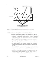
Page 118: ...t out of the way Lift the Carriage Assembly straight up and out When the assembly has cleared the chassis rotate it and place its backside on top of the chassis See Figure 7 6 CARAGE Connector Bottom...

Page 119: ...7 5 2 to retract the RLS into the rack 7 If the RLS is not rack mounted reposition it to its original location on the table 8 If the Carriage Assembly was replaced with a different unit proceed to Sec...

Page 120: ...be accessed Carousel Assembly 8mm Carousel PCBA DRVBAY Connector Ribbon Cable Figure 7 7 Carousel Assembly in the RLS 7 There are four Carousel mounting screws located on the bottom of the library Us...

Page 121: ...chassis and align its threaded mounting holes with the holes in the bottom of the chassis 2 If the RLS is not rack mounted carefully turn it upright 3 Using a No 2 Phillips screwdriver replace the fo...

Page 122: ...RLS 6227 SDLT P N 510172 02 6 RLS 8202 8236 8236C 8236CD 8236D LTO P N 510172 02 6 RLS 8204 8204D 8244 8244D 8404 LTO P N 510172 03 4 8404D 8444 8444D Cars of the Storage Array Figure 7 9 The Storage...

Page 123: ...connect PCBA Tools Required No 1 Phillips Screwdriver No 2 Phillips Screwdriver 5 64ths inch Hex Driver Small Mirror optional Small Flashlight optional 1 Remove the Carriage Assembly as described in S...

Page 124: ...hat cable to the right to unplug it from the Storage Array Assembly See Figure 7 11 Ribbon Cable Drive Platform Ribbon Cable Connector Storage Array Figure 7 11 Detailed view of the Ribbon Cable attac...

Page 125: ...of RLS Figure 7 13 Interconnect PCBA Mounting Screws Left Side 8 Remove the eight No 1 Phillips screws that secure the Interconnect PCBA from the left side of the chassis as shown in Figure 7 13 9 Lif...

Page 126: ...t hold the Sensor Slave Assembly in place see Figure 7 39 Grasp the assembly before removing the top last screw and then gently pull it out through the Front Panel Door 13 There are three or five mode...

Page 127: ...Mounting Screws 5 for RLS 42xx 6227 8202 8236 8236C 8236CD 8236D 3 for RLS 4470 shown with the Front of RLS Rear of RLS Storage Array Motor Access Hole Front of RLS Rear of RLS RLS 5244 8204 8204D 82...

Page 128: ...spect the Sensor Slave Assembly to be sure the LED at its edge is perpendicu lar to the plane of the board If it is not perpendicular the Sensor Slave Assem bly should be replaced 6 Align the Sensor S...

Page 129: ...7 24 to calibrate the RLS 7 9 3 Style B Chassis Storage Array Removal The Top Cover must be opened and the Carriage Assembly FRU must be removed to gain access to the Storage Array Tools Required No 2...

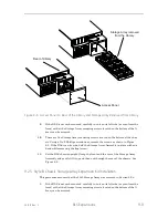
Page 130: ...the library See Figure 7 15 Access Panel Rear of Library Storage Array removed from the Library Figure 7 15 Access Panel on Rear of the Library and Storage Array Removed from Library 6 If the RLS is...

Page 131: ...v S Field Replaceable Units FRUs 7 27 8 Set the RLS chassis upright Grasp the front and the rear of the Storage Array Assembly and gently lift it up and then out through the rear of the chassis See Fi...

Page 132: ...step a small mirror and flashlight may be helpful to see the ribbon cable con nection 6 Reach into the back left corner of the drive bay and reconnect the ribbon cable that was detached from the conne...

Page 133: ...oval 1 Remove the Carriage Assembly by following Section 7 7 1 2 Use a No 2 Phillips screwdriver to remove the three screws that secure both rack mounting bracket to the sides of the RLS See Figure 7...

Page 134: ...the original pan head screws as is The Loctite residue is better than nothing 1 While supporting the Front Panel Door assembly with one hand slide the large link over the threaded standoff and using a...

Page 135: ...nits FRUs 7 31 Rack Mounting Brackets Front Panel Door Front Panel Door Linkage 2 sets Figure 7 16 Front Panel Door Assembly in the opened position Left Side Right Side 3 Screws 3 Screws Figure 7 17 T...

Page 136: ...7 32 Field Replaceable Units FRUs 501510 Rev S Front Panel Door Large Link Large Link Screw Loctite Small Link Small Link Screw Loctite Figure 7 18 Front Panel Door Linkage...

Page 137: ...bly IBM LTO 3 DFA Ext 501903 64 5 Tape Drive Assembly IBM LTO 4 DFA 501903 69 4 Tape Drive Assembly IBM LTO 4 DFA Ext 501903 84 3 Tape Drive Assembly IBM LTO 5 DFA 501903 85 0 Tape Drive Assembly IBM...

Page 138: ...7 34 Field Replaceable Units FRUs 501510 Rev S a straightened paper clip into the hole in the Front Panel Door See Figure 7 1 in Section 7 4...

Page 139: ...om of its travel horizontal position 4 Pull the drive all the way out and set it down gently 5 If the Tape Drive Assembly will not be replaced immediately use both hands to close the Front Panel Door...

Page 140: ...Push gently until it stops moving Disregard the Inventory Sentry alarm if it sounds as the inven tory will be rescanned when the Front Panel Door is closed CAUTION The RLS can be damaged by operating...

Page 141: ...nstalled drive will indicate a status of RANDOM or DISABLED 7 11 4 Drive Fillers If an RLS does not have all of its tape drives installed drive fillers must be installed in the empty drive bays The ap...

Page 142: ...il it is vertical and fits securely in the drive bay 4 To remove a drive filler gently pull it backwards and downward until it is free from the drive bay 7 12 Serial Control Panel PCBA P N 501507 01 6...

Page 143: ...rds and to the right to remove it Serial Control Panel PCBA INTER Connector on rear of Serial Control Panel PCBA Figure 7 23 INTER Connector and Cable 7 12 2 Serial Control Panel PCBA Replacement This...

Page 144: ...7 40 Field Replaceable Units FRUs 501510 Rev S 4 Reinstall the Carriage Assembly into the RLS as described in Section 7...

Page 145: ...the X Clear Emitter PCBA must be removed from the RLS before the drive bay PCBA can be replaced No calibration is required after replacing the Drive Bay PCBA FRU CAUTION The pins of the four Channel 1...

Page 146: ...3 Remove all the Tape Drives as described in Section 7 11 1 4 If the RLS is rack mounted follow the steps in Section 7 5 1 to extend the RLS out of the rack 5 Open the Top Cover of the RLS as describe...

Page 147: ...eight screws model spe cific that secure the Drive Bay Assembly to the bottom of the chassis Note that Carousel models use seven screws to secure the Drive Bay Assembly and Storage Array models use ei...

Page 148: ...ge Array STORAG connector and cable Figure 7 24 Drive Bay STORAG Connector and Cable Drive Bay Assembly Ribbon Cable Power Cable Top Cover Support Arm Top Cover Top Cover Support Arm Nuts 2 Cable Tie...

Page 149: ...Rev S Field Replaceable Units FRUs 7 45 INTER Connector Drive Bay PCBA Assembly Mounting Bracket Assembly Mounting Screws 3 POWER1 Connector POWER2 Connector Figure 7 26 Drive Bay PCBA Assembly Conne...

Page 150: ...s 501510 Rev S Drive Bay Assembly Mounting Screws 2 Rear of RLS Drive Bay Assembly Mounting Screws 3 Rear of RLS RLS 4000 6000 8116 8202 8216H 8236 8236D 8402H Models RLS 5116 5244 8204 8204D 8244 824...

Page 151: ...e Bay Assembly Mounting Screws Drive Bay Assembly Mounting Screws 2 Rear of RLS Drive Bay Assembly Mounting Screws 3 Rear of RLS RLS 4000 6000 8116 8202 8216C 8216CD 8216H 8236 8236C 8236CD 8236D 8402...

Page 152: ...ar of RLS Drive Bay Assembly Mounting Screws 7 RLS 41 42xx Models Rear of RLS Drive Bay Assembly Mounting Screws 8 RLS 44xx 62xx 8116 8202 8216C 81216CD 8216H 8236 8236C 8236CD 8236D 8402H Models Driv...

Page 153: ...ting bracket with its front side Figure 7 29 facing the Front Panel Door and the POWERx headers at the top as shown in Figure 7 26 2 Align the 13 mounting holes in the PCBA with those in its bracket a...

Page 154: ...sts in the top of the Drive Bay Assembly See Figure 7 25 11 Using a 1 4 inch hex nut driver or wrench replace the two nuts that secure the Top Cover Support Arm to the Drive Bay Assembly 12 Reconnect...

Page 155: ...f the RLS is rack mounted follow the steps in Section 7 5 1 to extend the RLS out of the rack 3 Using a No 2 Phillips screwdriver remove the three screws that retain the Ex ecutive Chassis to the Top...

Page 156: ...Us 501510 Rev S 3 Screws Figure 7 30 Executive Chassis Retaining Screws Executive PCBA POWER Connector INTER Connector DRIVEBAY Connector SENSOR Connector Interconnect PCBA Figure 7 31 The Executive a...

Page 157: ...hassis 2 While holding the board so it won t shift lift the Executive Chassis vertically and using a No 1 Phillips screwdriver replace the two flat head mounting screws See Figure 7 32 Lower the Execu...

Page 158: ...r replacing the Door Lock PCBA FRU Tools Required No 1 Phillips Screwdriver No 2 Phillips Screwdriver Chassis Screws 4 Door Lock PCBA Mounting Screws 2 Figure 7 33 Door Lock PCBA and Chassis Screws 7...

Page 159: ...3 3 Using a No 1 Phillips screwdriver reinstall the two door lock PCBA mounting screws that were removed earlier See Figure 7 33 4 Reconnect the ribbon cable to the SENSOR connector on the rear of the...

Page 160: ...form the RLS X Clear Emitter PCBA Right Side of the RLS Chassis Ribbon Cable Connector Figure 7 34 X Clear Emitter PCBA shown with Cover Removed 5 Cover Bracket Screws Front of RLS 2 X Clear Emitter...

Page 161: ...RLS 4124 8mm Please contact Technical Support RLS 4221 8mm Please contact Technical Support RLS 44XX 8mm Please contact Technical Support RLS 5116 SAIT Please contact Technical Support RLS 52XX SAIT...

Page 162: ...on the left side of the PCBA as seen from the front of the RLS See Figure 7 36 4 Disconnect the ribbon cable from the SENSOR connector on the right side of the PCBA as seen from the front of the RLS S...

Page 163: ...igure 7 38 The Sensor Slave PCBA Bracket and SENSOR Connector 1 Disconnect the ribbon cable from the SENSOR connector on the right side of the PCBA as seen from the front of the RLS See Figure 7 38 2...

Page 164: ...ct the ribbon cable to the SENSOR connector on the right side of the PCBA as seen from the front of the RLS See Figure 7 38 7 17 4 Sensor Master Assembly Replacement This procedure assumes the Sensor...

Page 165: ...1 8 The RLS Power Supply Module s must be removed before a DIA can be replaced The DIA type Quick Hot swappable installed can be changed at this time No calibra tion is required after replacing changi...

Page 166: ...straight back to disconnect it them from the connect or s on the Drive Bay PCBA Assembly Exercise extreme caution to prevent bending any of the pins on the Drive Bay PCBA Assembly 9 Remove the DIA s...

Page 167: ...ace Adapter flat head screws that secure the DIAs to the retaining bracket See Figure 7 40 7 Follow the instructions in Section 7 21 to reinstall the Power Supply Module s 8 Reconnect the SCSI cables...

Page 168: ...cure the re taining bracket to the library s chassis See Figure 7 41 8 Carefully lift the retaining bracket away from the library s chassis and set it aside 9 Carefully pull the DFA Duplex Cables blac...

Page 169: ...sing a No 2 Phillips screwdriver replace the three flat head screws that se cure the retaining bracket to the library See Figure 7 41 5 Carefully align the threaded hole in each fibre channel connecto...

Page 170: ...etion of this procedure 3 Unfasten the IPM by turning its two thumbscrew fasteners counter clockwise until the threads are fully disengaged 4 Grasp the bottom tabs and gently pull the IPM straight out...

Page 171: ...required after changing any Power Supply Module P N Description Package Qty Model Usage 510170 01 2 Power Supply 125W Full sized module 1 RLS 4124 4221 5116 8116 8216H only without Fibre Channel 5101...

Page 172: ...efully align the Power Supply Module with its opening 2 Push the Power Supply Module into the rear of the library until you feel it snap into place 3 Engage the two thumbscrew fastener s and turn them...

Page 173: ...fastener and turn it clockwise until it s fully engaged 5 Reattach the power cord 6 DO NOT push the Power Switch as this will turn off the RLS 7 22 Fixed Slots P N 500712 01 3 The Fixed Slots in RLS 4...

Page 174: ...ixed Slot with the notches is facing up 2 Align the mounting holes in the Fixed Slot with the threaded holes in the RLS and using a No 1 Phillips screwdriver replace the two pan head screws that were...

Page 175: ...its power on time The Filter Days value in the Configuration Advanced Changer menu determines how often the user will be reminded to check the Air Filter New units are set to 120 days An alert will b...

Page 176: ...lear the lip built into the Front Panel Door 3 Pull the right side of the filter towards the center of the Front Panel Door to clear the right side slot 4 Pull the left side of the filter towards the...

Page 177: ...rom any Fixed Slots Install an empty magazine at MA Make sure there is no magazine at MB Make sure there is to tape in the Handler Don t Care Conditions Which magazine is at the front of the Carousel...

Page 178: ...or Storage Array and the Handler will all move from time to time It will display a series of status messages as the calibration process progresses 7 24 3 Calibration Completion If the calibration comp...

Page 179: ...has just been revised as described above it will then immediately revise any satellite processor s firmware that is outdated Changing a FRU may also cause the Executive processor to update the firmwar...

Page 180: ...ws 95 98 XP NT or 2000 is required To update via the fibre channel interface a PC compatible computer running Windows NT or Windows 2000 is required NOTE Using a DOS system requires the use of Adaptec...

Page 181: ...he program s command syntax is as follows Upload Id Lun Host f filename Command Parameters Id Lun Host RLS Library SCSI address This address can be found using the scanscsi utility program The default...

Page 182: ...ion followed by a scanning of the RLS inventory 11 The FIRMWARE UPGRADE message will be cleared when the process has com pleted 12 Go to the Maintenance Display Revision menu The displayed Part Number...

Page 183: ...Press the enter key or click on the Upload Firmware button to begin the upload ing process 3 Note that after the upload begins browsing to another page will stop the firmware uploading process 4 Two d...

Page 184: ...8 6 Firmware Updating 501510 Rev S Figure 8 2 Sample of the Library Firmware Upload Progress Screen...

Page 185: ...plete a screen will appear that shows the old and new firmware information See Figure 8 4 Library uploading programming has finished Old firmware information Date 1 15 2003 Part number 700118 Revision...

Page 186: ...Qualstar RLS Library Serial Port RS 232 Serial Cable Figure 8 5 Host Computer Connected to RLS 8 5 1 RS 232 Cable Wiring User Host or PC RS232 Serial Female DB 9 Connector RLS Library RS232 Serial Fem...

Page 187: ...d NT users can use the Communications accessory program Hyper Terminal Figure 8 6 RLS Remote Front Panel Program Displayed in HyperTerminal Use the File Properties menu selection to configure the appl...

Page 188: ...8 10 Firmware Updating 501510 Rev S Figure 8 7 Properties Screen...

Page 189: ...meters for a baud rate of 38400 with 8 data bits no parity one stop bit and no flow control See Figure 8 8 Figure 8 8 Configure Screen Under the Properties Menu 8 5 4 VT100 Terminal Emulation Use the...

Page 190: ...e Updating 501510 Rev S Figure 8 9 Settings Screen Under the Properties Menu You may also consider ASCII Setup parameters to satisfy your display require ments Figure 8 10 ASCII Setup Screen under Set...

Page 191: ...ote Library Commands 8 5 6 Xmodem Firmware Download xdl The xdl command instructs the library to receive new RLS firmware via an object file on the remoter terminal computer using the XMODEM communica...

Page 192: ...ypically named 700118 000 00044 where 700118 represents the code set name and 00044 is the Ver sion Version 0 44 in this example A revision letter may follow the code set name Note It is very importan...

Page 193: ...NTFERNEN SIE DAS STROMKABEL BEVOR SIE MIT DER SERVICE ARBEIT BEGINNEN BENUTZEN SIE DIE RLS NIE WENN DIE TUERE OFFEN IST ODER DIE DECK BZW SEITENPLATTE ENTFERNT SIND 9 1 Introduction This chapter conta...

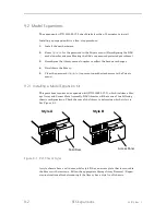
Page 194: ...ord Update to prevent unauthorized access to the Private menu 9 2 1 Installing a Model Expansion Kit This procedure requires one expansion kit P N 500829 07 2 which includes a Stor age Array and Senso...

Page 195: ...onal Small Flashlight optional 1 Remove the Carriage Assembly as described in Section 7 7 1 2 If possible remove all magazines or tapes from the magazines in order to protect the tape cartridges from...

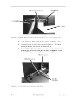
Page 196: ...Use diagonal cutters to cut the cable tie nearest the Executive PCBA that se cures the round power cable going to the Executive PCBA 7 Remove the Sensor Master Assembly by removing the two No 1 Philli...

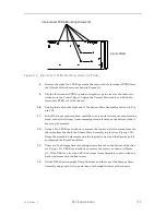
Page 197: ...e as seen from the front so that the Storage Array mounting screws located on the bottom of the li brary can be accessed 12 Using a No 2 Phillips screwdriver remove the lower or left two screws from t...

Page 198: ...accessed 2 While grasping the front and rear of the Storage Array guide the rear of the ar ray into the chassis Orient the array such that the connector is facing the drive bay or inside of the chassi...

Page 199: ...Once the Storage Array cable is connected give the cable a light tug to confirm it s firmly attached 11 Follow Section 7 11 2 to reinstall the Tape Drive s that were removed from the RLS If the drive...

Page 200: ...Fig ure 7 38 5 If the RLS is not rack mounted carefully turn it on its left side as seen from the front so that the Storage Array mounting screws located on the bottom of the li brary can be accessed...

Page 201: ...illips screwdriver remove the screws as shown in Figure 9 5 If the RLS is on its side hold the Storage Array Assembly in place with one hand while removing the final screw 11 Set the RLS chassis uprig...

Page 202: ...back to its upright position 8 Reconnect the cable to the right side of the Sensor Slave Assembly as shown in Figure 7 38 NOTE In the next step a small mirror and flashlight may be helpful to see the...

Page 203: ...Section 9 2 7 to reconfigure the RLS 9 2 7 Reconfiguring the Model Number NOTE If the RLS is restricted it may not be possible to change the RLS model number in the Configuration Advanced Changer Mech...

Page 204: ...nt Panel Door The Carriage remains stationary 9 Press the MENU key then press the EXIT key to exit the menu system The display indicates that the unit must be recalibrated Press the MENU key to return...

Page 205: ...501510 Rev S RLS Expansions 9 13 This page left blank intentionally...

Reviews: