


2-1
2 Printer Operation
2.1
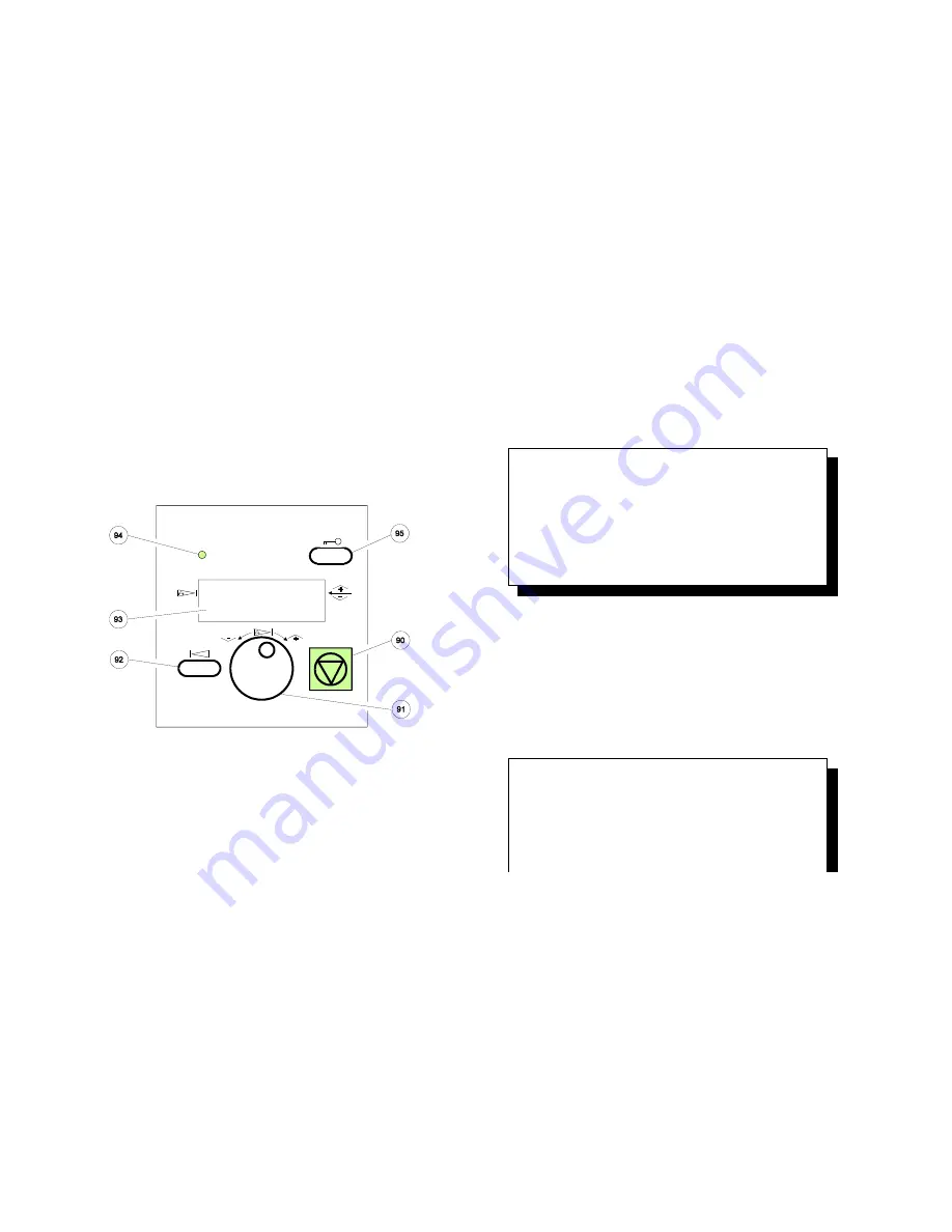
Control Panel
The control panel
S
gives information about the printer status
S
controls various parameter settings
S
allows manual control of the paper handling
2.1.1 Description of the two Indicators
S
The 4-line Liquid Crystal Display (LCD)
(93) indicates the current status of
the printer. If any error occurs (e.g. COVER OPEN) the resulting error
message will be displayed. While configuring the printer menu settings and
parameters appear on the display.
S
The green indicator lamp
(94) is lit if the printer is supplied with power by
setting the power ON/OFF switch to ON.
Printer Operation
2-2
2.1.2 Description of the LCD Indicator
The LCD Indicator gives information about the status of the printer.
In general it can be distinguished between:
S
ONLINE messages
S
OFFLINE messages
When the printer is in the
ONLINE
mode the display shows:
O N L
I
N E
(
1
)
1
6
.
0
0
x
1
2
I
N C H
L O W E R
-
-
> B O T T O M
In line two the selected paper format is shown and in line three the selected
paper input and paper output.
Note:
The value after
ONLINE
is the indication of the actual
PROFILE
.
When the printer is in the
OFFLINE
mode status information, error messages,
or menu messages are displayed.
Example: The display content after paper jam.
Note:
The printer status gets OFFLINE when a failure occurs.
O F F
L
I
N E
(
1
)
1
6
.
0
0
x
1
2
I
N C H
L O W E R
-
-
> B O T T O M