background image

E-4

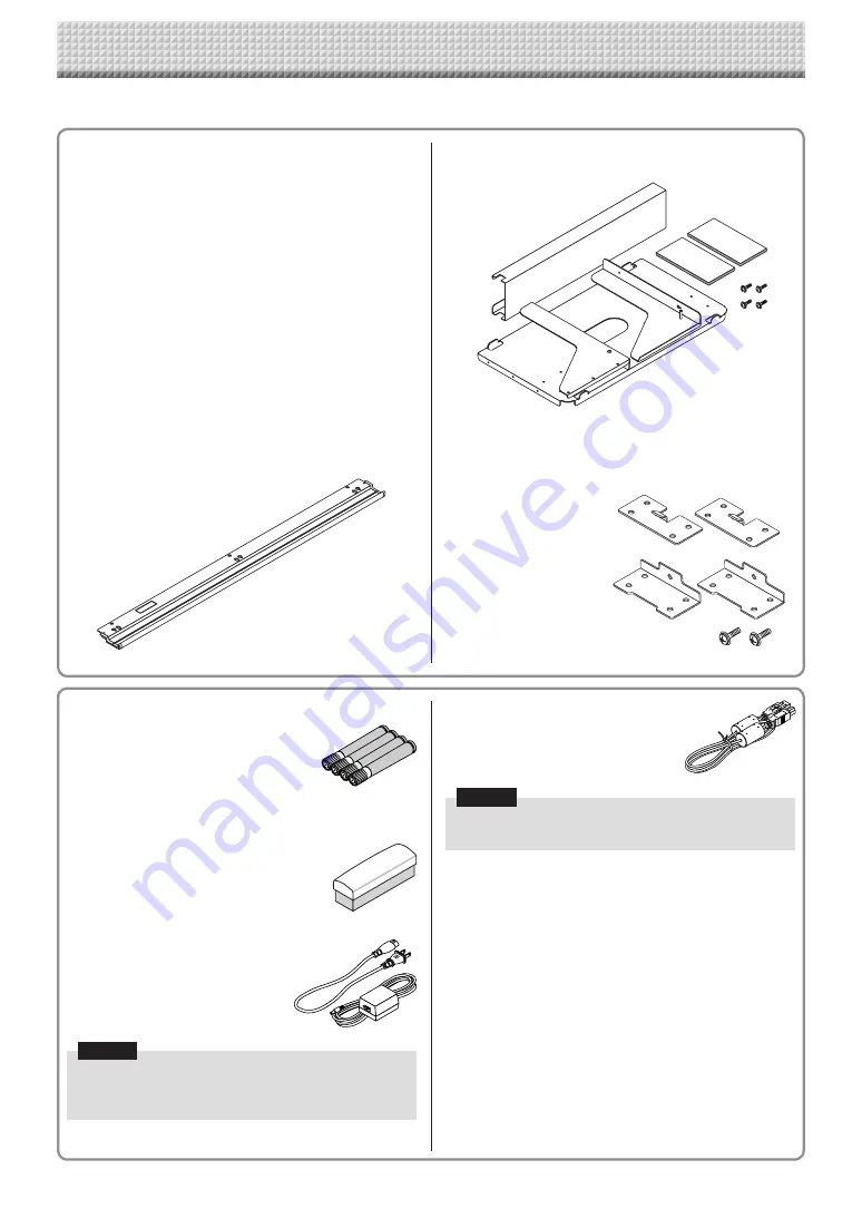
USB cable (type B 

 type A) [1]

[PLUS code 715258900]
Cable for connecting the main unit to a 
computer.
Used for making the device settings.

Notice

•  Do  not  use  this  cable  for  connection  to  the  printer 

(sold separately).

CD-ROM [1]

Includes the User’s Manual (this manual), Software Operation 
Manual  in  PDF  format,  and  this  unit’s  dedicated  software, 
“PLUS C-20 Software”.

User’s manual (in PDF format)

Includes instructions on using the set.

Software Operation Manual (in PDF format)

This  contains  instructions  for  combining  the  captureboard 
and computer screens using the PLUS C-20 Software.

Documents 

Important Safety Information [1]

Includes  instructions  to  be  heeded  in  order  to  use  the  set 
safely.

Assembly and Setup Manual

Includes  instructions  on  installing  the  set  and  connecting  it 
with the printer (sold separately).

Main unit [1]

Printer* [1] 

Please see the instruction manual of the printer for informa-
tion about the printer accessories. 
*  Depending  on  the  type  of  product  you  have  purchased, 

the printer may be sold separately.

Stand [1]

A mobile stand (with casters) for supporting the main unit. A 
printer table and AC adapter box are included. For the con-
tents  of  the  stand’s  package  and  instructions  on  assembly, 
see  the  stand’s  instructions  or  the  separate  Assembly  and 
Setup Manual.

Pen tray [1]

Pen  tray  fixing  screws  (M4  ×  20)  (temporarily  fastened  on 
main unit)
C-20S: 3 screws, C-20W: 4 screws
(See the Assembly and Setup Manual for assembly instruc-
tions.)

Wall mount printer table [1 set]

Bracket fixing screws (M4 × 8): 4
AC power adapter box: 1
Velcro: 2 sets
*  Sold separately.

Wall brackets [1 set]

These  are  brackets  for  mounting  the  main  unit  on  a  wall. 
(See the Assembly and Setup Manual.)

Upper wall brackets: 2

Lower wall brackets: 2

Main unit fixing screws (M4 × 12: 2)
*  Sold separately for some products.

Dedicated eraser [1]

Use this to erase the drawing. 

Captureboard Accessories 

Dedicated markers 

(One  each  of  black,  red,  blue,  and 
green) 
Use  these  markers  to  draw  on  the 
sheet surface. 

AC  power  adapter  (with  power 
cord) [1]

This is the power adapter for supply-
ing  power  to  the  captureboard  (See 
Page E-51).
(LTE36E-S2-3)

Notice

•  The  included  AC  power  adapter  and  AC  power  cord 

are exclusively for use with this unit. Never use them 
with other products.

The package contents are as described below. Please check before use. 

Package Contents

https://www.supplychimp.com/

Summary of Contents for C-20S

Page 1: ...your purchase of the PLUS Captureboard Please read this User s Manual carefully before use to take full advan tage of the functions of this product After you have finished reading the manual please ke...

Page 2: ...tached to it Doing so could result in malfunction Do not attach template sheets or paper to the sheet Do not copy while film type objects or papers are attach to the sheet Doing so could result in mal...

Page 3: ...captureboard E 9 Operation Steps E 10 When used as a Copyboard E 10 When used as a Captureboard E 11 Setting the Time E 12 Printing printer sold separately E 14 Preparing the Printer E 14 Basic Print...

Page 4: ...ng the main unit A printer table and AC adapter box are included For the con tents of the stand s package and instructions on assembly see the stand s instructions or the separate Assembly and Setup M...

Page 5: ...ly and Setup Manual Stand This stand supports the captureboard See the Assembly and Setup Manual Main unit Names of the Parts Pen tray Depending on the product you have purchased the printer may be so...

Page 6: ...ith a printer This illustration does not show the printer or connection cords Personal computer PC dedicated USB port Type B Connect this with the USB port type A of the PC Used to connect the capture...

Page 7: ...ing mounted or removed resulting in accidental injury due to the printer dropping or tipping over 1 Unplug the power cord from the wall power outlet then disconnect all the connection cords from the m...

Page 8: ...mory not recognized Lit red Off USB Memory storage problem USB memory not connected Memory is full Warning that disconnection of USB memory has been forgotten Reading error Flashing red Flashing red S...

Page 9: ...ns of the Captureboard LAN LAN Output to paper Viewing of images stored on the captureboard Captureboard s memory Projector Viewing of images stored on FTP server Printer Scanning with the C 20 Softwa...

Page 10: ...t have been supplied If anything other than the dedicated markers or eraser are used it may be impossible to erase the sheet or the sheet could get dirty To move the sheet manually see Moving the shee...

Page 11: ...nd switch off the power standby mode Note For details on operating PLUS C 20 Software and on connecting devices refer to the separate Software Operation Manual When combining the sheet surface drawing...

Page 12: ...switches each time the Save button is pressed Contents of setting mode displayed on display window First 2 digits Last 2 digits Christian year Month Day Hours Minutes 3 Set the setting mode s date and...

Page 13: ...setting Use the Color Print Increase and B W Print Decrease buttons to select 10 the month then press the Save button to enter The display switches to c4 setting of day Use the Color Print Increase an...

Page 14: ...per that can be used Notice Depending on the printer s specifications some time may be required for cleaning of the print head Switch on the power Press the power switch The power indicator lights Thi...

Page 15: ...y by hand The sheet can be moved either to the left or to the right Printing of the portion located around the sheet surface might not be possible Please see Effective reading size on Page E 5 Press t...

Page 16: ...he printer power Note When the Erase Reminder function is set to Enable When the ON Standby button is pressed the display window and all the indicators flash simultaneously the sheet automatically mov...

Page 17: ...memory devices protected by a security function cannot be used 3 USB flash memory devices with a capacity of over 32 GB cannot be used 4 If the USB flash memory device is divided into multiple partit...

Page 18: ...n the captureboard and a computer are connected by USB cable the data is stored in the main unit s internal memory Flashing indicator rotates sequentially during USB memory storage operation Display w...

Page 19: ...using a personal computer The name of the folder on the USB memory device is CB_Image Image files are stored in this folder By factory setting upon purchase image files are named PV xxx jpg JPEG file...

Page 20: ...the USB memory The disconnecting procedure depends on the computer s operating system For details refer to the computer s operating instructions or help files 1 Click the Hardware Removal icon that i...

Page 21: ...s Save button Doing so will cause the computer s operation to become unstable Do not press operation buttons on the captureboard while the captureboard s memory for computer storage is being accessed...

Page 22: ...device icon for the captureboard displayed as a C 20 is double clicked the captureboard s internal memory opens The CBImage file is the scanned image file jpg png or pdf according to setting The setu...

Page 23: ...The captureboard will not operate properly if the firewall is activated The following explanation assumes that the LAN cable has been connected and the various network settings have been completed Sa...

Page 24: ...FL flashes for about 5 seconds there is not enough space in the save to location Delete image files to pro vide space See pages E 27 and E 29 If the ON Standby button is pressed during the scanning op...

Page 25: ...mages are saved on the captureboard These images are downloaded transferred onto the computer connected on the network Downloading is possible even when the captureboard is in the standby mode but not...

Page 26: ...button is clicked it is checked and a preview image is displayed Download the image onto the computer 1 Click the Download button 2 The computer s Save as screen appears 3 Select the folder for savin...

Page 27: ...file name is clicked Check the scanned images using their preview images before deleting them Delete the file s Be sure to transfer important image files to a computer before deleting them data backu...

Page 28: ...lds on the verification screen Input the user name and password registered on the FTP server then click the Log In button Input the user name case sensitive and password case sensi tive then click the...

Page 29: ...the FTP server At step 4 on the previous page select the folder s or image file s to be deleted right click the mouse to display a pull down menu and select Delete At the verification screen click Yes...

Page 30: ...For instructions on the time setting see page E 12 Select the function number then press the Save button Press the Number of Copies button the function switches each time the button is pressed returni...

Page 31: ...e is set to 1 2 The amount of data is 1 4 that of when High Resolution is selected High Resolution The image file has the same resolu tion as the scanned image vertical horizontal size of 1 1 The pict...

Page 32: ...Off Printer Lit Time Day Stamp Format Selection of the format in which the date and time are displayed Examples of displays YYYY M D 2011 1 23 01 23 DD MMM YYYY 23 Jan 2011 01 23 MMM DD YYYY Jan 23 2...

Page 33: ...er and in this open the captureboard removable device 1 Double click the My Computer or Computer icon to open 2 Double click the captureboard a device displayed as a removable disk to open the capture...

Page 34: ...on a switching hub etc 2 Launch a web browser ex Internet Explorer on a computer con nected to network 3 In the address field input http followed by the IP address that was set then press the Enter ke...

Page 35: ...the network administrator before making the set tings Note Depending on the network being used the display speed and button response may be slow and operations may not be performed If this happens co...

Page 36: ...password can also be used for verification Once verification is validated the desired page is displayed See the respective pages in this manual for explanations CB Setup page E 38 Board File List page...

Page 37: ...s in the same way as you would on a computer The characters that can be input are restricted according to the item s type of setting See page E 41 Browse and Upload buttons See Header Footer Page E 39...

Page 38: ...orrect an error message is displayed Get Current Time When the Get Current Time button is clicked the display switches to the computer s current time This eliminates the need to make the cur rent date...

Page 39: ...r footer Click the radio buttons to select For instructions on creating images see page E 45 Header Browse When the Browse button is clicked the computer s Browse Files screen opens Select the image t...

Page 40: ...g in to the FTP server and save image files Blank FTP Password This is the password registered on the FTP server This is required for the captureboard to log in to the FTP server and save image files...

Page 41: ...ber characters that can be input is the same as for the administrator s user name admin Password Set the password The limit to the number characters that can be input is the same as for the administra...

Page 42: ...Network Storage Set whether or not to enable or disable transfer of image files to network storage folder for saving Board or FTP Server to a computer or FTP server Notice When set to Invalid the net...

Page 43: ...e Disk Check button is clicked checking of the network stor age memory starts When checking is completed the results of the check are displayed If a warning is displayed format the disk Disk Format Wh...

Page 44: ...tton to display the network reset number The network reset number can be viewed when User Setting is selected with administrator authority The display switches as follows each time the Color Print Inc...

Page 45: ...s Paint etc to paste images input characters etc to create the image When saving save in JPEG format with a size within the maximum size Registering created images on the capture board Example Here we...

Page 46: ...the power outlet and then plug it in again Security protec tion The operation is set to Disable in the security settings Change the setting of the desired item to Enable See page E 42 Color printing...

Page 47: ...t other net work error An error other than one indicated by L1 to L4 has occurred Unplug the power cord from the power outlet then plug it back in Network settings reset error An error has occurred in...

Page 48: ...your nearby PLUS Corporation sales office dealer or store Condition Please Check Printer Related The captureboard s power turns on but the printer s power does not Check whether the printer s power p...

Page 49: ...splay window lit press the Number of Copies button repeatedly to display on the display window 2 Press the Color Print button for a color print the B W Print button for a black and white print Test pr...

Page 50: ...ion 300 dpi or equivalent No print colors 16 or grayscale Printer interface Conforming to USB 2 0 standards Added functions Clock Used for the timestamp and for file dating properties PC connection Im...

Page 51: ...upplied with the printer AC power adapter supplied To wall power outlet Appearance of printer is for illustration purposes Note The AC power adapters of accessories and printers that have been verifie...

Reviews: