background image

Copyright Planika Sp. z o.o.  

www.planikafires.com 


IG0139#02 

30.07.2018 


57 

7.3.


Ignition of the main burner 

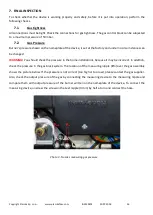
Information about the ignition of the main burner can be found in the Manual. 

7.3.1.


First ignition of the device after installation or after modifications 

WARNING!


After installation of the device or after service work you should light up the device for the first 

time without inserting the front glass. If necessary, drain the gas pipe.  

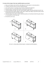
Follow the procedure below:  


If necessary, remove the glass. 


You should start the ignition as described in the Manual.. 


I f the main burner does not light up: 

o


Reset the system by pressing the remote control buttons simultaneously "arrow up" and "down 
arrow". 

o


Repeat the ignition until the main burner lights up. 

WARNING!


After each failed attempt ignition system must be reset.  


If  after  several  attempts  the  burner  still  does  not  light,  refer  to  the  table  of  error  messages  (see. 
Chapter Troubleshooting). 


In the first place middle section of the device will be lit for 100% of its power, and when it detects the 
ionization,  device  goes  on  50%  of  its  power.  The  detection  must  take  place  within  10  seconds. 
Otherwise, the device goes into failure mode. After about one minute from the start of the middle 
section, the second valve supplying gas to the side section of the hearth turns on, and the unit returns 
to its full capacity. You can hear then the characteristic "click".  


Make sure that the hearth is burning all the time. 


If the hearth is not burning all the time, reset the system as described and repeat the ignition procedure 
until the furnace will burn continuously. 

WARNING!


The  system  can  be  reset  to  re-ignition  only  three  times  in  a  row.  Then  the  system  will  be 

permanently blocked and you have to wait half an hour before another ignition attempt. 


Please refer to the table of error messages, if this does not happen after a few attempts. 


Disconnect the device from the power supply. 


Then mount the glass as described in section 5.12.1. 


Repeat the ignition procedure several times and perform the checks described in section 7.3.2. 


Since then, the hearth should light up without problems. 

WARNING!


Always wait 3 minutes before retrying ignition of the device. You cannot make any modifications 

to the gas assembly. 

Summary of Contents for MONROE 900 F

Page 1: ...o o www planikafires com IG0139 02 30 07 2018 1 INSTALLATION MANUAL MONROE 900 F MONROE 900 LF FR MONROE 900 LFR G20 G25 Natural Gas G30 G31 Propane Butane Propane Produced by Planika Sp z o o Bydgoska 38 86 061 Brzoza Poland ...

Page 2: ...tion of the fireplace housing with a front glass F 17 5 6 2 Installation of the fireplace housing with two sided glazing LF FR 17 5 6 3 LFR Installation of the fireplace housing with a tripartite glazing LFR 18 5 7 Fireplace housing with platform 18 5 7 1 Fireplace housing in combination with bottom decorative frame 18 5 7 2 Fireplace housing without decorative frame 20 5 7 3 Adjustment of the upp...

Page 3: ...ntrol 53 6 2 1 Wired connection 53 6 2 2 The wireless connection through the protocol Modbus 55 7 FINAL INSPECTION 56 7 1 Gas tightness 56 7 2 Gas Pressure 56 7 3 Ignition of the main burner 57 7 3 1 First ignition of the device after installation or after modifications 57 7 3 2 The Hearth 58 7 4 Flame 58 7 5 Checklist 59 8 MAINTENANCE 59 8 1 Spare parts 60 9 DELIVERY 60 10 WARRANTY 61 11 TROUBLES...

Page 4: ...d by local law CE Declaration of conformity We hereby declare that both the design and construction of a gas heating device manufactured by Planika Sp z o o with registered office at Bydgoska 38 86 061 Brzoza Polska meet the essential requirements contained in the Directive and the Ordinance on gas appliances Product Convection space gas heater with closed combustion chamber equipped with concentr...

Page 5: ... and their connection to the gas system and the flue system is identical The user also has the option of choosing the version of the interior of the fireplace and control it by using remote control supplied together with the device through automation system of intelligent buildings or use for this purpose a built in thermostat unit 3 SAFETY WARNING It is mandatory to make sure to carefully read th...

Page 6: ...of use of the device additional ventilation and ventilation of the room is recommended to quickly remove the characteristic smell fire resistant paint WARNING When you first start your device the installer should perform the leak test on all gas connections check the connections of all elements of the system including the proper connection to the concentric air combustion system and check the corr...

Page 7: ...or the construction of fireplace housing equipment use only non flammable materials e g non combustible and heat resistant plates or materials made of stone Non combustible materials must be used to complete both external as well as internal part of the housing and for completing the wall at which the device will be placed Strictly follow the minimum distance between non combustible walls of the h...

Page 8: ...d and certified cables connecting gas flexible hose Replace them at least every 2 years Flexible hose supplying gas to the unit should be located away from sharp edges and hot surfaces Avoid bends and twists of flexible connections along the whole length Note that the gas cylinder LPG should be installed in well ventilated areas LPG gas is heavier than air and its accumulation on the substrate can...

Page 9: ...lied with the sensor 3 4 Seismic sensors Planika fireplaces are additionally equipped with seismic detectors that automatically switch off the fireplace when any shocks eg Earthquake are detected that endanger the safe use of the device WARNING The sensor must always be pointing up By default it is mounted so that it works properly with a gas valve installed vertically ...

Page 10: ...unt the gas valve in a non upright position 90 degrees to the left or right it is necessary to change the position of the seismic sensor so that it is always mounted in a vertical position Installation of the gas valve 90 degrees to the left Installation of the gas valve 90 degrees to the right ...

Page 11: ... be disposed in accordance with local regulations 5 INSTALLATION WARNING The installer should be certified and qualified professional in the field of installation of gas and electric The device must be installed in accordance with the relevant applicable national and local regulations and to follow the rules or instructions contained in this installation manual 5 1 Type of gas Before installing ma...

Page 12: ...cted from moisture and dust These factors may cause irreparable damage to the individual components The pipe supplying gas to the fireplace should be equipped with a ball valve with a diameter of 1 2 inch The individual elements of the gas installation cannot be sealed using Teflon tape or PTFE tape The gas valve on the gas pipe must be installed in accordance with applicable national regulations ...

Page 13: ...ht the interior of the housing and allows you to control it from the remote control and automation of intelligent building The exact description of additional lighting control or other electrical receiver is described in the user manual A built in relay L can be used to control any AC receiver AC 230V 0 5A The relay has neutral polarity Connector B is used for connection of an additional fan or op...

Page 14: ...minimum required distance from the unit Outlet pipes were installed according to the manual The wall before which the device will be placed at was made of non flammable and heat resistant material Do not use any additional insulation or wrap the device in any other material The unit was in a stable position and was placed on a flat leveled base This will be particularly important if the adjustable...

Page 15: ...ousing execution Before performing the installation protect the elements of the gas control system from dirt Installation of the fireplace according to current building regulations should be made of non combustible materials including floor and ceiling If the fireplace is powered by natural gas NG exhaust grille should be placed under the ceiling of the room where the device is installed Power liq...

Page 16: ...en the upper circular hole outlet and the ceiling of the room Front hole of the fireplace housing must allow easy installation and removal of the front glass after placing the fireplace wall Secure the gas assembly and gas pipes against cement and mortar Decorative strips frames etc should be installed after the completion of all required structural work if possible You should avoid using masking ...

Page 17: ...replace housing with a front glass F WARNING The minimum height for the location of the inspection hatch beneath the product is 430mm In case of the location of the inspection hatch next to the product the height is minimum 215mm 5 6 2 Installation of the fireplace housing with two sided glazing LF FR ...

Page 18: ...izontal surface located in front of the glazing must be constructed of non flammable and heat resistant material 5 7 1 Fireplace housing in combination with bottom decorative frame You must follow the correct notch in the horizontal parts of the installation according to the drawings below Adjust each other height of the device with decorative frame and mounting kit constructive elements so that t...

Page 19: ...Copyright Planika Sp z o o www planikafires com IG0139 02 30 07 2018 19 Fireplace with two sided glazing Fireplace with tripartite glazing Decorative frame Decorative frame ...

Page 20: ...is allowed thanks to the installation of the horizontal part of the fireplace housing constructed of non combustible and heat resistant material near the machine shaft with a maximum material thickness of 30 mm To properly construct fireplace housing you should pay attention to make appropriate cut in the horizontal part of the fireplace housing according to the drawings below Fireplace with two s...

Page 21: ...racket there are notches E i e indicating the standard thickness 20mm and 30mm Setting a notch on a par with the edge of the body of the fireplace provides a horizontal position of the bracket In order to ensure correct adjustment of the brackets you must use the level Tighten the nuts M6 C Adjust the height of each unit and installation kit fireplace housing components so that the lower part of t...

Page 22: ...position of the fireplace s top decorative frame in the range from 0 to 40mm comparing to the default assembly To change the position of the upper decorative frame of the fireplace you should Loosen all nuts that press the frame to the fireplace body Position and level the frame at a fixed height Tighten all nuts that press the frame to the fireplace body WARNING Take care that the frame does not ...

Page 23: ...pection hatch will be replaced by another one the installer must take care about the correct and safe positioning of the gas assembly inside To place an inspection hatch in the wall of the fireplace you should make a hole in it with dimensions of 205x255 mm which can be made in horizontal or vertical position Place an inspection hatch In this hole together with gas assembly bearing in mind that it...

Page 24: ...ion hatch Attach the handle with the gas assembly components B see Picture 5 using self drilling screws Make sure that in there is no dirt in the gas pipes as well as connections at the gas assembly Connect the gas pipe to the gas assembly Connect the mains voltage 230 V with grounding to the power cord ended with cube running from the gas assembly WARNING Connecting the device to the electrical n...

Page 25: ...e wall of the building as well as the roof If necessary you can also use the existing chimney for the combustion air supply concentric flue system is designed for indoor use and therefore cannot be used outside with the exception of terminals that are made for this purpose In all these cases you must comply with regulations in force in the country Use the concentric system supplied by Planika This...

Page 26: ...al components of the air combustion system use supplied with the concentric flue system metal clamp providing additional rigidity of the entire system which operates in underpressure 5 9 2 Recommendations for proper installation of the concentric flue system To install concentric flue system you should Construct the system starting from the device with mounted adapter Perform passage for the needs...

Page 27: ...mented by additional protective insulation against the ingress of moisture into the building If the concentric flue system is located near the combustible walls elements you must ensure a minimum distance of 100 mm from flammable materials Installation of the concentric flue system should always start with the one meter vertical section minimum height at the outlet of the device Total height of th...

Page 28: ...em should be connected together by using special clamps supplied with the combustion air system which provide additional rigidity If necessary the individual elements of the concentric flue system can be stabilized by using wall brackets Picture 9 Example of system configuration with wall terminal ...

Page 29: ...he device Maximum length of the concentric flue system must not exceed 12 meters The maximum number of bends at an angle of 90 cannot be higher than 4 To calculate the maximum length of vertical and horizontal sections of concentric flue system you must first count the number of planned arches 45 and 90 Next calculate the length of concentric flue system corresponding to the number of applied arch...

Page 30: ...Copyright Planika Sp z o o www planikafires com IG0139 02 30 07 2018 30 Picture 10 Example of system configuration with roof terminal ...

Page 31: ... specificity of the geographical location of the fireplace installation weather conditions wind directions and strength and the presence of other buildings in the area Table 1 Concentric flue system configuration with a roof terminal WARNING The above configuration Table is also applicable in the case of connection of the fireplace to an existing chimney A properly selected flue gas restrictor sho...

Page 32: ...allation of the fireplace and after the final installation of concentric flue system access to it is only possible through the fireplace combustion chamber In such a case to replace the flue gas restrictor you should Disassemble the front glass of the fireplace Unscrew the nuts holding the plate located in the upper part of the combustion chamber Disassemble the plate ...

Page 33: ...res com IG0139 02 30 07 2018 33 Replace the flue gas restrictor paying special attention to place it properly in specially designed brackets Mount the plate in the upper part of the combustion chamber Install the front glass of the fireplace ...

Page 34: ...the existing chimney In case of connecting to an existing chimney the following requirements apply Approved only for use in combination with a special chimney set supplied by the manufacturer The internal dimension of the existing chimney should be at least 200 x 200 mm and the vertical height should be up to 12 meters The total length of the horizontal pipe must not exceed a maximum length of 4 m...

Page 35: ...ral elements of the building During the design and installation of concentric flue system you should pay special attention to the location of the exhaust outlet in relation to the structural elements of the building Height near a roof window Location near a roof window Location under the balcony and below the edge of the roof ...

Page 36: ...Copyright Planika Sp z o o www planikafires com IG0139 02 30 07 2018 36 Height above the ground level Location near the door and window openings Location near shading projections ...

Page 37: ... edge of the obstacle 2 In case of exhaust outlet from the concentric flue system situated at a distance of 1 5 to 3m from the obstacle the outlet chimney must be placed at least at the level of the upper edge of the obstacle 3 In case of exhaust outlet from the concentric flue system situated at a distance of 3 to 10 meters from the obstacle the outlet chimney must be placed at least 0 3 m above ...

Page 38: ...e the fireplace housing and direct the stream of hot air passing through the body of the device you can use two openings inside the casing located on its upper part You should use flexible connections for this purpose to move the hot air outside the housing When using the openings in the upper part of the unit in order to distribute the hot air from the body of the fireplace it is necessary to mak...

Page 39: ... as not to obscure the ionization and ignition electrodes as well as outlets of the hearth and to allow free flow of air around the hearth Otherwise it may result in incorrect operation of the fireplace The ceramic elements or decorative stones cannot adhere to the glass as it may cause its damage Decorative set of filling the combustion chamber attached to the unit consists of Vermiculite Vermicu...

Page 40: ... Sp z o o www planikafires com IG0139 02 30 07 2018 40 Set of decorative logs Ceramic logs which will be placed on the 3 top burners have suitable recesses at their bottom part that match the shapes and sizes of burners ...

Page 41: ...ior of the combustion chamber should be filled with all supplied decorative stones Make sure that the ionization and ignition electrodes as well as the space around them remained free so that no decorative element touches any of the electrodes Make sure that the gap between the burner and the tray surrounding the burner is not blocked by any decorative elements Make sure to avoid spilling the powd...

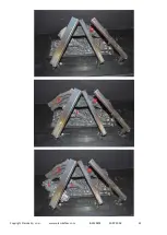
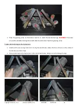
Page 42: ...m D to J During the identification follow the traces of burns on the surface of the branches and their shape Place ceramic logs on the burner and vermiculite tray in given order which is appointed by letters of alphabet Logs cannot completely cover the shape of the burner which may cause the main burner not igniting properly This can lead to incorrect operation of the device and the device may qui...

Page 43: ...Copyright Planika Sp z o o www planikafires com IG0139 02 30 07 2018 43 ...

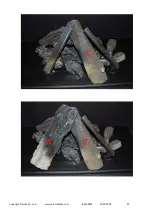
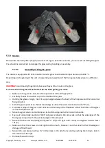
Page 44: ...around the ionization and ignition electrodes should remain free from glowing wires To place decorative logs on the top burners Identify all the ceramic logs from A to C During the identification follow the traces of burns on the surface of the branches and their shape Place ceramic logs on the top burners in the order shown below taking care not to damage the logs ...

Page 45: ...Copyright Planika Sp z o o www planikafires com IG0139 02 30 07 2018 45 ...

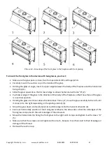
Page 46: ...of the glass Holding the glass at angle insert its upper edge between the body of the fireplace and the horizontal fixing strip 1 Slide the glass upwards so that its lower edge is above the lower decorative frame D 2 Push lower edge of the glass in the direction of the body of the fireplace so that the surface of the glass is in vertical position 3 Move the glass down and carefully set its bottom ...

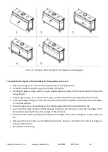
Page 47: ...ass in the direction of the body of the fireplace so that the surface of the glass is in vertical position Holding the glass at all times above the decorative frame B move the glass carefully to the left until it stops or to the right depending on the glazing version 3 Move the glass down and carefully set its bottom edge inside the horizontal handle 4 Even out horizontally position of the front g...

Page 48: ...s lower edge is placed above the lower decorative frame B 2 Push lower edge of the glass in the direction of the body of the fireplace so that the surface of the glass is in vertical position Move the glass down and carefully set its bottom edge inside the horizontal handle 3 Even out horizontally position of the front glass relative to the side walls so that the side edges of the front glass comp...

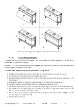
Page 49: ...nd the glasses are cooled down to room temperature Carefully mount the suction cup in the middle of the glass Remove the side pressure stripes A by lifting them up and moving them towards the center of the front glass 1 Unscrew the screws B pressing a horizontal strip C by holding the front glass 2 Move the pressure strip to the left and then move down to dismantle it 3 Lift the front glass vertic...

Page 50: ... then move down to dismantle it Lift the front glass pane vertically to the top so that its bottom edge is above the decorative frame B 2 Holding the glass at all times above the decorative frame B move carefully the glass making sure that its right edge does not hit the decorative frame C 3 Drag the lower part of the front glass to each other so that its lower edge is beyond the contour of the ho...

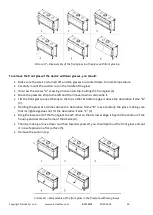
Page 51: ...s 1 Move the pressure strip to the left and then move down to dismantle it Lift the front glass vertically to the top so that its bottom edge is above the decorative frame B 2 Drag the lower part of the front glass to each other so that its lower edge is beyond the contour of the housing and decorative frame of the device 3 Then by making a move down and then towards yourself you should pull out t...

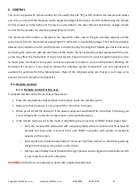
Page 52: ...on of corrosion If you need to replace the individual system components use only original parts available for purchase from the Manufacturer Plugs of the individual wires are chosen in such way as to prevent incorrect connection components 6 1 Remote controls 6 1 1 Remote control for the user To prepare remote control to use follow these steps Place the two batteries AA attached to the device insi...

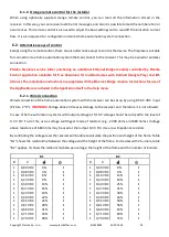
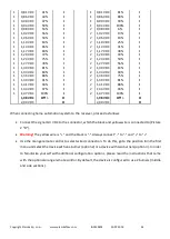
Page 53: ...cluded in the Application itself in the Help menu 6 2 1 Wired connection Wired connection of the home automation system with the receiver can be set up by using DC 0 3 VDC input Picture 2 D WARNING Voltage above 3V causes damage to the receiver and therefore it is not allowed In case of home automation systems with output voltage of 0 10 V voltage should be reduced to the level of 0 3 V DC To do t...

Page 54: ...1 1 41 VDC 94 I 2 1 41 VDC 88 I 1 1 44 VDC 97 I 2 1 44 VDC 94 I 1 1 47 VDC 100 I 2 1 47 VDC 100 I 1 98 VDC Off O 1 98 VDC Off O 2 00 VDC O 2 00 VDC O When connecting home automation system to the receiver proceed as follows Connect the signal 0 3 V DC to the connector which the black and yellow wire is connected to Picture 2 D Warning The yellow wire is and the black is Always connect to and to Us...

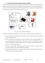
Page 55: ... using a communication module do the following Using the remote control check whether the place where you want to place a communications module is within range of the receiver Place the remote control in the right place and test the sensitivity of the received signal RSSI To do this simultaneously press the On Off button and the arrow down button The displayed value must be between 20 to 80 see Us...

Page 56: ...cumstances can be changed WARNING You should check the pressure in the home installations because it may be incorrect In addition check the pressure in the gas block system The location of the measuring nipple Pin over the gas assembly shows the picture below If the pressure is not correct too high or too low please contact the gas supplier Also check the output pressure of the gas by connecting t...

Page 57: ...d when it detects the ionization device goes on 50 of its power The detection must take place within 10 seconds Otherwise the device goes into failure mode After about one minute from the start of the middle section the second valve supplying gas to the side section of the hearth turns on and the unit returns to its full capacity You can hear then the characteristic click Make sure that the hearth...

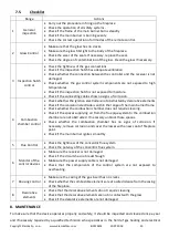
Page 58: ...ccording to the information contained in Section 7 3 1 Check the operation of the burner from a cold state If the sparks are detected between the electrodes the central hearth should ignite within a few seconds The image of the flame and the correct transfer of the flame to the side sections of the burner can be evaluated properly only when the front glass is mounted If the ignition of the main bu...

Page 59: ...hin the range of the main burner flame Check whether the combustion chamber does not require cleaning Check if the spaces supplying air from the flue pipe system to the combustion chamber are not obstructed If necessary unblock those spaces Check whether the combustion chamber has no signs of corrosion If necessary remove corrosion and cover the losses with a new coat of fireplace paint Check if t...

Page 60: ...es use of the remote control and annual maintenance Additionally the installer must provide the user with the following information and instructions In case of perceived irregularities in the operation of the device immediately close the gas valve and contact your installer in order to avoid dangerous situations Indicate the user to the location of the gas valve Pay attention to the preventive mea...

Page 61: ...does not cover decorative insulation panels decorative ceramic logs and glass The use of the fireplace insert way of connecting to the chimney and operating conditions must be in accordance with the user manual The basis for the free repair covered by warranty is a warranty card Warranty Card will expire without a date stamps signatures as well as the amendments made by unauthorized persons Custom...

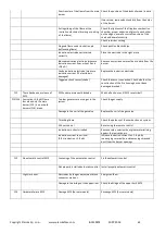
Page 62: ...e communication cable F02 Overheating of the receiver 60 c above room temperature Poor ventilation by the receiver Improve ventilation at the receiver The receiver is in contact with the hot parts Move the receiver so that it does not touch the hot parts F03 Internal NTC sensor of the receiver is not working properly Damaged receiver Replace Receiver F04 External NTC sensor is not working properly...

Page 63: ...ction of the fire housing has not been damaged cracked F12 There has been no release of ESYS ESYS under permanent blockade Wait half an hour until ESYS resets itself F13 F14 ionisation 0 8 µA Flame loss when only the main burner F13 is on or both burners F14 are on Too low gas pressure or no gas in the system Check the gas supply Damage to the coil of the gas valve Replace the coil of the gas valv...

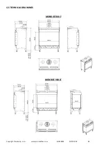
Page 64: ...Copyright Planika Sp z o o www planikafires com IG0139 02 30 07 2018 64 12 TECHNICAL DRAWINGS MONROE 900 F MONROE 900 LF ...

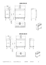
Page 65: ...Copyright Planika Sp z o o www planikafires com IG0139 02 30 07 2018 65 MONROE 900 FR MONROE 900 LFR ...

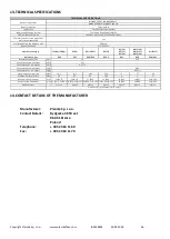
Page 66: ...tput m3 h Consumption on low output m3 h Consumption on max output kg h Consumption on low output kg h Maximum burner pressure mbar 10 5 24 0 19 0 23 0 27 27 26 Minimum burner pressure mbar 5 0 9 5 9 5 10 2 9 9 9 Nozzle of the main burner mm 1x Ø1 75 1x Ø1 5 1x Ø1 5 1x Ø1 5 1x Ø1 2 1x Ø1 1 1x Ø1 05 Nozzles of the side burner mm 1x Ø1 75 2x Ø1 5 1x Ø1 5 2x Ø1 35 1x Ø1 5 2x Ø1 35 1x Ø1 5 2x Ø1 35 3x...

Page 67: ...idelines contained in the Installation and User s Manuals I hereby declare that having read the User s Manual and the Guarantee Conditions Date and legible signature of the Buyer INSTALLER Name Address Tel fax Date of commissioning I hereby declare that the gas fireplace installed by my Company has been installed in accordance with the applicable building regulations and in accordance with the gui...

Page 68: ...ure and seal of the chimney sweeper Date signature and seal of the chimney sweeper Date signature and seal of the chimney sweeper Date signature and seal of the chimney sweeper Date signature and seal of the chimney sweeper Date signature and seal of the chimney sweeper Date signature and seal of the chimney sweeper Date signature and seal of the chimney sweeper Date signature and seal of the chim...

Reviews: