Copyright Planika Sp. z o.o.
www.planikafires.com
IG0139#02
30.07.2018
53
6.1.2.
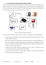
Orange remote control for the installer
When using optionally supplied orange remote control, you can read all the information stored in the
receiver. In this way, you can recover last 20 error messages, and also it is possible to read the number of error
occurrences. This remote control is also used to adjust the basic settings and to read off the ionization current
flow. It is also required for configuration of wired home automation system connection.
6.2.
Alternative ways of control
Except using the remote control, there are also alternative ways to control the device. The fireplace is suitable
for connection to a home automation system that can connect to the receiver. This may be a wired or wireless
connection.
Planika fireplaces can be (after purchasing an additional Ethernet Bridge module) controlled by Planika
Control application available for free download for mobile devices with Android (Google Play) and iOS
(iTunes). The installation instructions are supplied with the Ethernet Bridge module. Instructions for use of
the Application are included in the Application itself in the Help menu.
6.2.1.
Wired connection
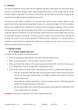
Wired connection of the home automation system with the receiver can be set up by using DC 0-3 VDC input
(Picture 2 "D").
WARNING!
Voltage above 3V causes damage to the receiver and therefore it is not allowed.
In case of home automation systems with output voltage of 0-10 V voltage should be reduced to the level of
0-3 V DC. To do this, use a voltage switchgear made of resistors (e.g., 2200 ohms and 680 ohms). Voltage
above resistance of 680 ohms may be used at the output 0-3 V DC. Use a low impedance resistors.
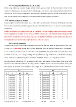
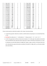
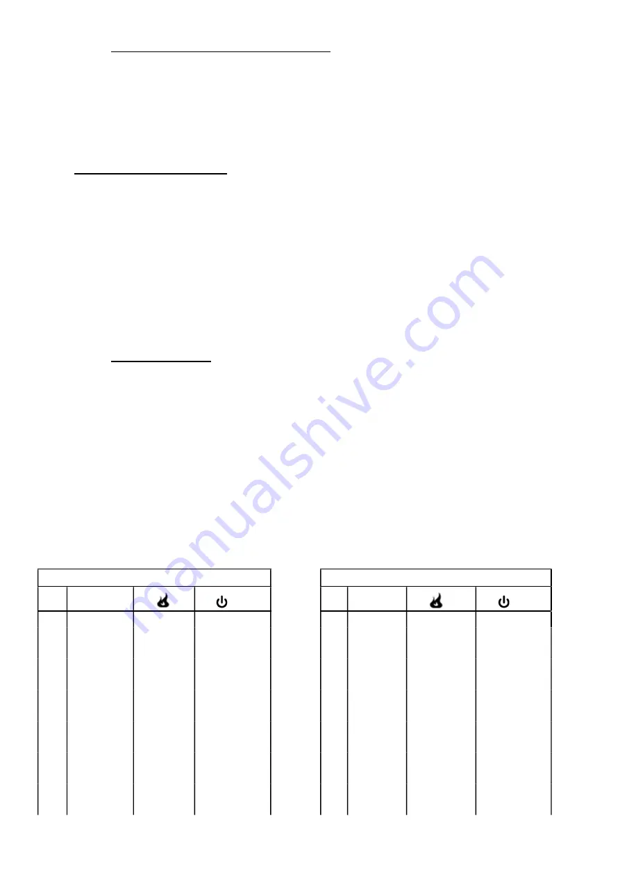
By controlling the voltage level the receiver will be able to calculate the position and height of the flame. Table
"B1" shows the relationship between the voltage and the height of the flame. For devices with 2 burners, table
"B2" applies. It shows the relationship between voltage, the height of the flame and the number of burners.
B1
B2
B
V
B
V
1
0,00 VDC
0%
I
1 0,00 VDC
0%
I
1
0,08 VDC
3%
I
1 0,08 VDC
6%
I
1
0,16 VDC
6%
I
1 0,16 VDC
13%
I
1
0,23 VDC
9%
I
1 0,23 VDC
19%
I
1
0,30 VDC
13%
I
1 0,30 VDC
25%
I
1
0,37 VDC
16%
I
1 0,37 VDC
31%
I
1
0,43 VDC
19%
I
1 0,43 VDC
38%
I
1
0,49 VDC
22%
I
1 0,49 VDC
44%
I
1
0,55 VDC
25%
I
1 0,55 VDC
50%
I
1
0,61 VDC
28%
I
1 0,61 VDC
56%
I
1
0,66 VDC
31%
I
1 0,66 VDC
63%
I
1
0,71 VDC
34%
I
1 0,71 VDC
69%
I
1
0,76 VDC
38%
I
1 0,76 VDC
75%
I

