PDP-5010FD
136
1
2
3
4
1
2
3
4
C
D
F
A
B
E
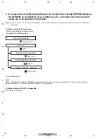
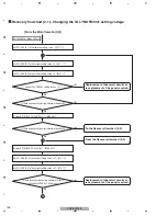
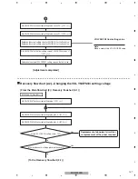
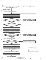
Recovery flowchart (2-1)...Changing the VOL YNOFS3/4/1 setting voltage
[From the Main flowchart (2)]
Set VOL YNOFS1 to the tentative setting value. / [VY1
***
]
Set VOL YNOFS3 to the current setting value +4. / [VY3
***
]
Replacement of abnormal circuits or
re-replacement of the panel re
q
uired
Replacement of abnormal circuits or
re-replacement of the panel re
q
uired
N
o
Yes
Yes
To the Recovery flowchart (2-2)
From the Recovery flowchart (2-2)
Yes
Current VOL YNOFS3 setting value > 137?
N
o
Is there erroneous discharge (abnormal dead cell)?
N
o
Is there erroneous discharge (abnormal dead cell)?
Set VOL YNOFS4 to the current setting value +4. / [VY4
***
]
Display RST MASK 22 (Cyan 3SF). / [MKS S72]
Set VOL YNOFS3 to the current setting value +47. / [VY3
***
]
Set VOL YNOFS4 to the current setting value +47. / [VY4
***
]
RST MASK 16 (Green 1023+)
Display RST MASK 15 (Red 1023+). / [MKS S65]
N
o
Yes
Is there erroneous discharge (abnormal lit cell)?
(Check on the PANEL 1-ADJ menu.)
B
Summary of Contents for PDP-5010FD
Page 19: ...PDP 5010FD 19 5 6 7 8 5 6 7 8 C D F A B E ...
Page 20: ...PDP 5010FD 20 1 2 3 4 1 2 3 4 C D F A B E 4 BLOCK DIAGRAM 4 1 OVERALL WIRING DIAGRAM 1 2 ...
Page 23: ...PDP 5010FD 23 5 6 7 8 5 6 7 8 C D F A B E ...
Page 35: ...PDP 5010FD 35 5 6 7 8 5 6 7 8 C D F A B E ...
Page 167: ...PDP 5010FD 167 5 6 7 8 5 6 7 8 C D F A B E ...
Page 178: ...PDP 5010FD 178 1 2 3 4 1 2 3 4 C D F A B E 10 6 PANEL CHASSIS SECTION ...

