PDP-5010FD
64
1
2
3
4
1
2
3
4
C
D
F
A
B
E
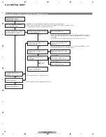
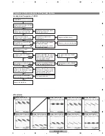
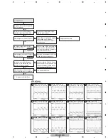
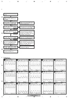
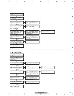
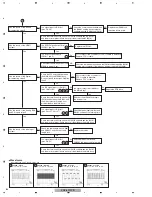
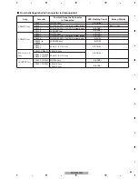
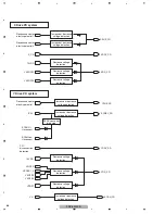
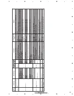
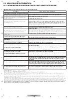
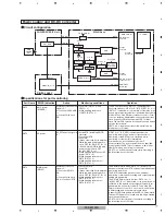
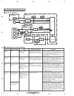
5.3.2 PD (POWER-DOWN) DIAGNOSIS OF FAILURE ANALYSIS
Connectors
disconnection detection
Q1219 to Q1224
Q2217 to Q2224
Q121
8
to Q1224,Q1226
Q2217 to Q2224
IC2601,IC2603,D2604
Q2320 to Q2325,Q2330,Q2332,Q2334
Q2320 to Q2325,Q2330,Q2332,Q2334
Q2320 to Q2325,Q2330,Q2332,Q2334
Q2320 to Q2325,Q2330,Q2332,Q2334
Red LED
Flashing
Count
Operating
PD
Defective Assy
PD Outline
Checkpoint
Possible Defective Part
Remarks
2
PO
W
ER
PO
W
ER SUPPLY Unit
PO
W
ER SUPPLY Unit
X DRI
V
E Assy
V
SUS U
V
P
Failure in the PO
W
ER SUPPLY Unit
X SUS BLOCK
V
SUS-SUSOUT and SUSOUT-
SUSG
N
D are short-circuited.
Y DRI
V
E Assy
Y SUS BLOCK
V
SUS-SUSOUT and SUSOUT-
SUSG
N
D are short-circuited.
V
SUS-SUSOUT and SUSOUT-
SUSG
N
D are short-circuited.
V
SUS-SUSOUT and SUSOUT-
SUSG
N
D are short-circuited.
3
SCA
N
SCA
N
Assy
V
H U
V
P
SCA
N
IC
SCA
N
IC
X DRI
V
E Assy
X SUS BLOCK
Y DRI
V
E Assy
Y SUS BLOCK
V
H DC/DC converter
Connectors
disconnection
detection
C
N
2001,C
N
2301
DIGITAL Assy
C
N
3509
4
SC
N
-5
V
SCA
N
Assy
C
N
2
8
01,C
N
2901,C
N
2902,C
N
3001,
C
N
3002,C
N
3101
SCA
N
IC
IC5
V
U
V
P
IC5
V
DC/DC
Q2764,D276
8
,R2764
SCA
N
IC
Y DRI
V
E Assy
6
Y-DCDC
Y DRI
V
E Assy
VN
OFS U
V
P
Y MSK BLOCK
LMSK is short-circuited.
VN
OFS DC/DC
D2606,Q2709,Q2710
V
prst U
V
P
YPRST Regulator
Q2604,Q2605,IC2602
15
V
DD U
V
P
15
V
DC/DC
Q2662,R2669
V
KOFS1_2 U
V
P
Y MSK BLOCK
LMSK is short-circuited.
V
KOFS1_2 Regulator
Q2705,Q2702
V
KOFS3 U
V
P
Y MSK BLOCK
LMSK is short-circuited.
V
KOFS3 Regulator
Q2706,Q2703
V
KOFS4 U
V
P
Y MSK BLOCK
LMSK is short-circuited.
EXT_PD line: Open
EXT_PD line: Open
It becomes "U
N
K
N
O
W
" except
above-mentioned PD detection
condition.
V
KOFS4 Regulator
Q2707,Q2704
7
Y-SUS
Y DRI
V
E Assy
Center electric potential
detection PD
Y RESO
N
A
N
CE BLOCK
Q2106 to Q2109,Q2111,Q2113,
D2104 to D2107
8
ADRS
ADDRESS Assy
ADDRESS RESO
N
ACE BLOCK
V
ADR U
V
P
TCP
V
ADR U
V
P
C
N
1601,C
N
1602,C
N
1
8
01,C
N
1
8
02
C
N
3501 to C
N
350
8
C
N
1202 to C
N
1206
C
N
2302 to C
N
2306
Connectors
disconnection
detection
DIGITAL Assy
X DRI
V
E Assy
Y DRI
V
E Assy
9
XDRI
V
E
X DRI
V
E Assy
Connectors
disconnection
detection
C
N
1001
DIGITAL Assy
C
N
3510
P4
C
N
3
8
01
Each PD line of ModuleUcom
ModuleUcom can not
detection
10
X-DCDC
X DRI
V
E Assy
Connectors
disconnection detection
Connectors
disconnection detection
Connectors
disconnection detection
C
N
1201
15
V
DD U
V
P
X SUS BLOCK
L1201,R1217
15
V
DC/DC
Q1402
V
XKOFS1 U
V
P
V
XKOFS1 Regulator
Q1405,Q1406
X OFFSET BLOCK
Q1302,Q1304
V
XKOFS2 U
V
P
V
XKOFS2 Regulator
Q1403,Q1404
X OFFSET BLOCK
Q1301,Q1303
11
X-SUS
X DRI
V
E Assy
Center electric potential
detection PD
X RESO
N
A
N
CE BLOCK
Q110
8
,Q1116,Q1112,Q1119
12
15
DIG-DCDC
U
N
K
N
O
W
DIGITAL Assy
DIGITAL Assy
3.3
V
, 2.5
V
, 1.1
V
U
V
P, O
V
P, OCP
5.1
V
OCP
Abnormality in the DC-DC converter
control IC
Periphery of the DC-DC converter
Abnormality in 5.1
V
input
(include abnormality in the protection fuse)
IC3
8
01
FU3
8
01
Q3
8
41, Q3
8
61, Q3
88
1
L3
8
41, L3
8
61, L3
88
1
R3
8
20, R3
8
4
8
, R3
8
6
8
, R3
888
U
V
P: Under
V
oltage Protect , O
V
P: Over
V
oltage Protect
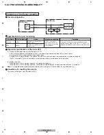
Prediction of failure symptoms when a PD (power-down) is generated
Summary of Contents for PDP-5010FD
Page 19: ...PDP 5010FD 19 5 6 7 8 5 6 7 8 C D F A B E ...
Page 20: ...PDP 5010FD 20 1 2 3 4 1 2 3 4 C D F A B E 4 BLOCK DIAGRAM 4 1 OVERALL WIRING DIAGRAM 1 2 ...
Page 23: ...PDP 5010FD 23 5 6 7 8 5 6 7 8 C D F A B E ...
Page 35: ...PDP 5010FD 35 5 6 7 8 5 6 7 8 C D F A B E ...
Page 167: ...PDP 5010FD 167 5 6 7 8 5 6 7 8 C D F A B E ...
Page 178: ...PDP 5010FD 178 1 2 3 4 1 2 3 4 C D F A B E 10 6 PANEL CHASSIS SECTION ...

