PDP-5010FD
116
1
2
3
4
1
2
3
4
C
D
F
A
B
E
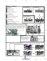
1
Disconnect cables, connectors, as required.
2
Remove the two screws.
3
Remove the two screws.
4
Remove the POD cover.
5
Remove the POD stay A with PCB.
MAIN Assy
4
POD Assy
POD cover
POD stay A
2
3
3
2
5
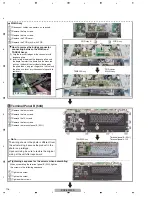
How to remove the bridge connector
connecting between the MAIN and
TANSHI Assys
(1) Grip the two short edges of the connector with
longnose
pliers.
(2) Insert a finger between the longnose pliers and
the board to protect the board and the mounted
parts on the board from accidental damage by
the pliers then, using your finger as a fulcrum and
the pliers as a lever, pry the connector upward to
remove
it.
TANSHI Assy
MAIN Assy
×
4
Terminal Panel B (50U)
3
1
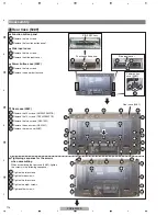
Remove the four screws.
2
Remove the two screws.
3
Remove the 10 screws.
4
Remove the four screws.
5
Remove the terminal panel B (50U).
5
Terminal panel B (50U)
TANSHI Assy
Terminal panel A (U)
3
1
3
3
2
2
3
3
3
3
3
1
2
3
3
4
4
4
4
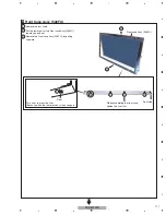
The wiring shown in the photo is different from
the actual wiring, because the product in the
photo is a prototype.
Upon servicing, be sure to restore the original
wiring of the unit after repair work.
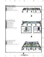
Note:
1
Tighten the screw.
2
Tighten the screw.
3
Tighten other screws.
When assembling the terminal panel B (50U), tighten
the screws in the following sequence:
Tightening sequence for the screws when assembling
TANSHI Assy
MAIN Assy
Summary of Contents for PDP-5010FD
Page 19: ...PDP 5010FD 19 5 6 7 8 5 6 7 8 C D F A B E ...
Page 20: ...PDP 5010FD 20 1 2 3 4 1 2 3 4 C D F A B E 4 BLOCK DIAGRAM 4 1 OVERALL WIRING DIAGRAM 1 2 ...
Page 23: ...PDP 5010FD 23 5 6 7 8 5 6 7 8 C D F A B E ...
Page 35: ...PDP 5010FD 35 5 6 7 8 5 6 7 8 C D F A B E ...
Page 167: ...PDP 5010FD 167 5 6 7 8 5 6 7 8 C D F A B E ...
Page 178: ...PDP 5010FD 178 1 2 3 4 1 2 3 4 C D F A B E 10 6 PANEL CHASSIS SECTION ...

