PDP-5010FD
109
5
6
7
8
5
6
7
8
C
D
F
A
B
E
6.2.4 INITIALIZE
N
I
I T I
L
A
I Z E
I D
S
E
M A S
L
L
+
(
)
K
I N
E V E
V
–
D 1
3
1
0 6 0
– N T V
H
A
–
B
1
5
10
15
16
1
5
10
15
20
25
30
35
40
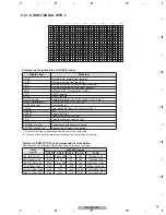
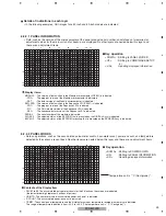
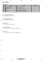
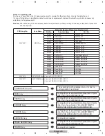
To configure sidemask level (To adjust the values, input signal is required).
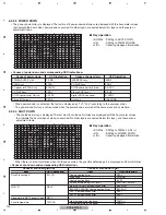
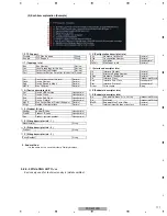
• To reset each memory values to factory default values. Factory command is "FST".
• When the configuration is set to <NO> and the [ENTER/SET] key is pressed, no action is taken and the menu returns to
previous screen.
• When the configuration is set to <YES> and the [ENTER/SET] key is pressed for 5 seconds, the reset action executes.
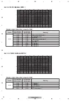
Display
Content
RS-232C
SIDE MASK LEVEL <=>
Adjust Side Mask level (Adjustable range: 000 to 255)
SML
N
I
I T I
L
A
I Z E
A T
D
A
R E S
T
E
I N
F
A L
S E T U P
< = >
V
–
D 1
3
1
0 6 0
O
: N
– N T V
H
A
–
B
1
5
10
15
16
1
5
10
15
20
25
30
35
40
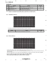
6.2.4.2 FINAL SETUP (+)
6.2.4.1 SIDE MASK LEVEL (+)
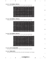
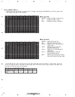
Be sure to disconnect and connect the AC cable after FINAL SETUP.
When replacing the MAIN Assy, the FINAL SETUP is required.
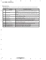
Operation item
No.
Function
Content
RS-232C
6.2.4.1 SIDE MASK LEVEL (+)
Configure the color of the side mask.
SML
6.2.4.2 FINAL SETUP (+)
Initialize flash memorys on virgin product status
FST
6.2.4.3 HMG/HG SERVICE MODE
Enter HMG/HG SERVICE MODE
−−−
6.2.4.4 Wide XGA AUTO <=>
Exclusively used for technical analsyis.
−−−
Note:
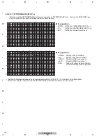
When there is an altered history due to an open TRAP SW, if the "DISPLAY" key is held for at least
5 seconds on the above menu, the altered history will be cleared and the unit will be back to normal.
Summary of Contents for PDP-5010FD
Page 19: ...PDP 5010FD 19 5 6 7 8 5 6 7 8 C D F A B E ...
Page 20: ...PDP 5010FD 20 1 2 3 4 1 2 3 4 C D F A B E 4 BLOCK DIAGRAM 4 1 OVERALL WIRING DIAGRAM 1 2 ...
Page 23: ...PDP 5010FD 23 5 6 7 8 5 6 7 8 C D F A B E ...
Page 35: ...PDP 5010FD 35 5 6 7 8 5 6 7 8 C D F A B E ...
Page 167: ...PDP 5010FD 167 5 6 7 8 5 6 7 8 C D F A B E ...
Page 178: ...PDP 5010FD 178 1 2 3 4 1 2 3 4 C D F A B E 10 6 PANEL CHASSIS SECTION ...

