PDP-5010FD
50
1
2
3
4
1
2
3
4
C
D
F
A
B
E
No
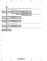
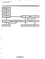
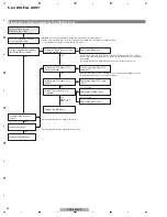
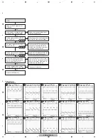
Is the waveform normal when the
voltage is applied to the panel?
(See the oscilloscope photos.)
Are all the connectors properly
connected?
Reconnect the connectors.
No
Set the VXKOFS1 voltage correctly.
B
D
NG
Yes
NG
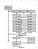
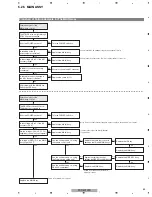
Is the VXKOFS1 set voltage
correctly set?
No
Set the VXKOFS2 voltage correctly.
Yes
Is the VXKOFS2 set voltage
correctly set?
Yes
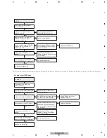
Another Assy may be in failure.
X DRIVE Assy
No
Replace the FFC cables.
Replace the DIGITAL Assy.
Replace the X DRIVE Assy.
NG
NG
Yes
Yes
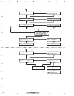
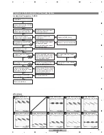
Is the input signal normal?
(See the oscilloscope photos.)
No
Are all the connectors properly
connected?
Reconnect the connectors.
No
C
NG
Yes
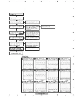
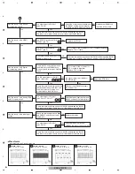
Is the TCP control signal normal?
(See the oscilloscope photos.)
Yes
ADDRESS Assy
Replace the panel chassis.
Replace the DIGITAL Assy.
Yes
No
NG
Replace the FFC cables.
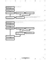
Is the input signal normal?
(See the oscilloscope photos.)
No
Summary of Contents for PDP-5010FD
Page 19: ...PDP 5010FD 19 5 6 7 8 5 6 7 8 C D F A B E ...
Page 20: ...PDP 5010FD 20 1 2 3 4 1 2 3 4 C D F A B E 4 BLOCK DIAGRAM 4 1 OVERALL WIRING DIAGRAM 1 2 ...
Page 23: ...PDP 5010FD 23 5 6 7 8 5 6 7 8 C D F A B E ...
Page 35: ...PDP 5010FD 35 5 6 7 8 5 6 7 8 C D F A B E ...
Page 167: ...PDP 5010FD 167 5 6 7 8 5 6 7 8 C D F A B E ...
Page 178: ...PDP 5010FD 178 1 2 3 4 1 2 3 4 C D F A B E 10 6 PANEL CHASSIS SECTION ...

