PDP-5010FD
130
1
2
3
4
1
2
3
4
C
D
F
A
B
E
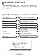
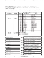
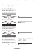
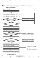
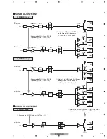
Preparation before adjustment
[Replacement with the panel for service is completed.]
[To the Main flowchart (1)]
Turn the unit on. / [PO
N
]
Enter Factory mode. / [FAY]
Set PM/B1-B5 to CLEAR (to clear the pulse meter). / [CPM]
Set HR-MTR to CLEAR (to clear the hour meter). / [CHM]
Turn the unit off. / [POF]
Turn the unit on. / [PO
N
]
Enter Factory mode. / [FAY]
Display RST MASK 01 (white). / [MKS S51]
Select
V
ideo 60-Hz sequence. / [
V
FQ S03]
*
To store the [
V
FQ S03] command in memory, transmit it
after displaying the mask.
Note:
If you perform the adjustment by RS-232C commands, the following commands must be added
before going to the main flowchart (1):
[PAV S00]
: To set panel drive mode to Factory
[VFQ S03]
: To set Drive Sequence to
V
ideo 60-Hz
[WBI S01]
: To temporarily reset the Panel
W
B adjustment value to default (
W
BI S00 cancels this setting.)
[PGR S00]
: To set the gamma R value to that for Factory mode
[PGG S00]
: To set the gamma G value to that for Factory mode
[PGB S00]
: To set the gamma B value to that for Factory mode
[DIZ S03]
: Dither O
N
, L dither O
N
, noise OFF.
[$1
8
00000001]
: LUT mode O
N
[$1000003F00]
: Reset active control OFF.
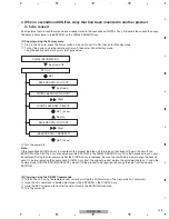
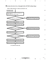
Procedures for resetting
corrections for change
over time
Perform aging for 5 minutes.
Enter the initial values for the panel for service.
Procedures for stabilizing the
panel before adjustment
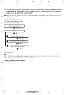
Note:
α
V
sets adjustment value to 10.
AWV9999-
VOF=35V
VRP=170V VY3=1
8
4+
α
V VY4=200
Indication example of the adjustment label
of service panel
Data 07/05/24 Chassis CXX99999
Time 1
8
:27 Pnl FTEST123456
Hour Meter
_ _ _ _ _ _ _ _ _ _ _ _
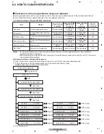
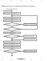
H
V
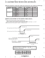
OL SUS (127 fixed) / [
V
SU 127]
V
OL OFFSET (
V
OF adjustment voltage) reduction / [
V
OF
***
]
V
OL RST P (
V
RP adjustment voltage) reduction / [
V
RP
***
]
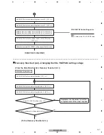
V
OL XPOFS1 (0
8
7 fixed) / [
V
X1 0
8
7]
V
OL XPOFS2 (140 fixed) / [
V
X2 140]
V
OL Y
N
OFS3 (
V
Y3 adjustment voltage) re10 / [
V
Y3
***
]
V
OL Y
N
OFS4 (
V
Y4 adjustment voltage) reduction / [
V
Y4
***
]
V
OL Y
N
OFS1 (
V
Y3 adjustment voltage) reduction-21 / [
V
Y1
***
]
Summary of Contents for PDP-5010FD
Page 19: ...PDP 5010FD 19 5 6 7 8 5 6 7 8 C D F A B E ...
Page 20: ...PDP 5010FD 20 1 2 3 4 1 2 3 4 C D F A B E 4 BLOCK DIAGRAM 4 1 OVERALL WIRING DIAGRAM 1 2 ...
Page 23: ...PDP 5010FD 23 5 6 7 8 5 6 7 8 C D F A B E ...
Page 35: ...PDP 5010FD 35 5 6 7 8 5 6 7 8 C D F A B E ...
Page 167: ...PDP 5010FD 167 5 6 7 8 5 6 7 8 C D F A B E ...
Page 178: ...PDP 5010FD 178 1 2 3 4 1 2 3 4 C D F A B E 10 6 PANEL CHASSIS SECTION ...

