PDP-5010FD
79
5
6
7
8
5
6
7
8
C
D
F
A
B
E
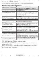
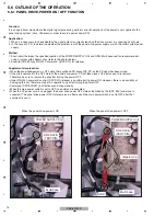
5.6.4 TRAP SWITCH
For video data transmission inside this Plasma Display, digital signals are used. Therefore, this unit adopts the HDCP
(High-bandwidth Digital Content Protection) system for copyright protection. This unit is also provided with a detection switch
(TRAP switch) that will prohibit the unit from being turned on again "if the rear case of the unit is accidentally opened," in order
to prevent the panel technology from being leaked out.
The TRAP switch is disabled while the unit is turned off.
When performing internal diagnosis of the PDP, fix the switch to the OFF position using adhesive tape before turning on the
unit. After servicing, be sure to remove the adhesive tape.
WHEN THE TRAP SWITCH IS ACTIVATED
When the TRAP switch is activated, the red and blue LEDs will light.
In order to deactivate the TRAP switch, close the upper plate of the unit or fix the TRAP switch to the OFF position in the
manner described above.
Then, follow procedures (1) or (2) below:
(1) Deactivating with the remote control unit
• Enter Factory mode.
• Proceed to the INITIALIZE layer of Factory mode. Hold the DISPLAY key pressed for more than 5 seconds.
(2) Deactivating with the RS-232C command
• Send the CTM (cancel) command.
Outline and Notes
TRAP switch
POD Assy
MAIN Assy
Summary of Contents for PDP-5010FD
Page 19: ...PDP 5010FD 19 5 6 7 8 5 6 7 8 C D F A B E ...
Page 20: ...PDP 5010FD 20 1 2 3 4 1 2 3 4 C D F A B E 4 BLOCK DIAGRAM 4 1 OVERALL WIRING DIAGRAM 1 2 ...
Page 23: ...PDP 5010FD 23 5 6 7 8 5 6 7 8 C D F A B E ...
Page 35: ...PDP 5010FD 35 5 6 7 8 5 6 7 8 C D F A B E ...
Page 167: ...PDP 5010FD 167 5 6 7 8 5 6 7 8 C D F A B E ...
Page 178: ...PDP 5010FD 178 1 2 3 4 1 2 3 4 C D F A B E 10 6 PANEL CHASSIS SECTION ...

