PDP-5010FD
124
1
2
3
4
1
2
3
4
C
D
F
A
B
E
8.2 BACKUP OF THE EEPROM (DIGITAL ASSY)
Outline
Adjustment data are stored in the EEPROM (4K) on the DIGITAL Assy in the production process. Those adjustment data are
also automatically stored in the EEPROM (for backup) on the PANEL SENSOR Assy.
If the DIGITAL Assy is replaced, those adjustment data for backup can be copied from the EEPROM on the PANEL SENSOR
Assy to a new DIGITAL Assy.
Backed up data
• Drive voltage adjustment value
• Hour-meter count
• Pulse-meter count
• Panel white balance adjustment value
• Serial No.
• Drive waveform adjustment value
• P-ON counter value
• PD/SD histories
How to copy backup data
1. When the DIGITAL Assy is replaced with one for service (usual service)
Adjustment data can be restored by copying the data backed up in the PANEL SENSOR Assy to the EEPROM on a new
DIGITAL Assy.
The EEPROM on the new DIGITAL Assy has no adjustment data, and the EEPROM for backup in the PANEL SENSOR Assy
has adjustment data. After replacing the DIGITAL Assy, enter PANEL FACT. mode, display the PANEL INFORMATION page,
then check if "NO DATA!" is set for "DIG. EEP" and "ADJUSTED" is set for "BACKUP". Then, proceed in the following steps:
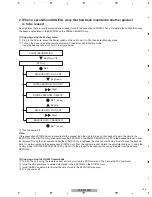
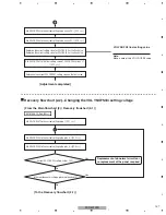
(1) Copying, using the Factory menu
1
Plug in the AC cord, press the Power switch on the unit to set it to ON, then enter Standby mode.
2
Turn on the power, using the remote control unit, then enter Panel Factory mode.
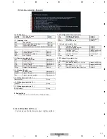
Copy the backup data, as shown in the figure below.
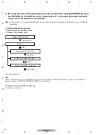
(2) Copying, using the RS-232C commands
1
Turn on the unit, using the remote control unit or by issuing the PON command. Then issue the FAY command.
2
Issue the BCP command to transfer the data stored in the EEPROM for backup.
3
Turn the power off.
3
Turn the power off.
• After the DIGITAL Assy is replaced with one for service, be sure to check if "NO DATA!" is set for "DIG. EEP" on the PANEL
INFORMATION page of the PANEL FACT. mode.
• If copying of the backup data fails in the above procedure, the red LED lights, and the blue LED flashes, as a warning that
no backup data were copied.
• If both the DIGITAL and PANEL SENSOR Assys are to be replaced, first replace the PANEL SENSOR Assy, turn the unit on
and back off again, then replace the DIGITAL Assy.
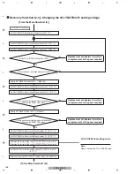
PANEL INFORMATION
ETC. (+)
BACKUP DATA : NO OPRT
Key Down 7th
SET
Right
SET (5 sec)
BACKUP DATA : TRANSFER
Summary of Contents for PDP-5010FD
Page 19: ...PDP 5010FD 19 5 6 7 8 5 6 7 8 C D F A B E ...
Page 20: ...PDP 5010FD 20 1 2 3 4 1 2 3 4 C D F A B E 4 BLOCK DIAGRAM 4 1 OVERALL WIRING DIAGRAM 1 2 ...
Page 23: ...PDP 5010FD 23 5 6 7 8 5 6 7 8 C D F A B E ...
Page 35: ...PDP 5010FD 35 5 6 7 8 5 6 7 8 C D F A B E ...
Page 167: ...PDP 5010FD 167 5 6 7 8 5 6 7 8 C D F A B E ...
Page 178: ...PDP 5010FD 178 1 2 3 4 1 2 3 4 C D F A B E 10 6 PANEL CHASSIS SECTION ...


