DVR-533H-S
82
1
2
3
4
1
2
3
4
C
D
F
A
B
E
ERR RATE :
∗
.
∗
e-
∗
• While the User Operation screen is displayed, press the ESC then DISP keys, then the DIG/ANA
key twice, in that order.
• While subscreen 1 of the first screen is displayed, press the DIG/ANA key.
[How to enter]
Press the ESC key.
[How to quit]
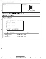
(3) Simple Error Rate Measurement (Subscreen 2)
[Measurement procedures]
1
Display subscreen 2.
2
Load the Test disc (GGV1025).
3
Judge the results of the error rate measurement by
referring to Table 1 on next page.
[Tips]
During VR mode playback, the average value of the past 10 VOBUs is displayed. During DVD-Video or Video mode
playback, the average value of the past 256 sectors is displayed.
During VR mode playback, the speed ratio of the drive (/: normal, no indication: double speed) is also displayed.
Subscreen 2
1) Frequency Difference (Freg Diff)
How much tuning is off is monitored, as shown below:
2) AGC voltage (AGC Volt)
The gain controlled by the tuner is monitored to infer the input electric field intensity.
(The accuracy of inference differs depending on the product.)
Field Intensity
AGC Volt
Intense field area
(Clear image)
Less intense field area
(Noise may be generated.)
Weak field area
(Much noise. EPG/VPS/PDC sometimes cannot be
obtained.)
Very weak field area
(Image damaged. EPG/VPS/PDC cannot be obtained.)
70 dB
µ
or more
3300 mV or more
50 dB
µ
or more
70 dB
µ
or less
3100 - 3300mV
30 dB
µ
or more
50 dB
µ
or less
2600 - 3100mV
30 dB
µ
or less
2600 mV or less
Tips:
For good reception, the field intensity must be 50 dB
µ
or more (AGC Volt 3100 mV or more).
For accurate measurement, use a field intensity meter.
High
Input Frequency
Display
Low
Just Tune
Low 1
Low 2
Center
High
Summary of Contents for DVR-531H-S
Page 17: ...DVR 533H S 17 5 6 7 8 5 6 7 8 C D F A B E ...
Page 41: ...DVR 533H S 41 5 6 7 8 5 6 7 8 C D F A B E I CN4501 To HDD CN9014 H 4 5 ...
Page 47: ...DVR 533H S 47 5 6 7 8 5 6 7 8 C D F A B E SIDE B SIDE B TUNB ASSY A A A CN101 VNP2004 A ...
Page 59: ...DVR 533H S 59 5 6 7 8 5 6 7 8 C D F A B E SIDE B SIDE B I I POWER SUPPLY UNIT I ...

