DVR-533H-S
118
1
2
3
4
1
2
3
4
C
D
F
A
B
E
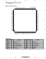
No. Pin Name
I/O
Function
No. Pin Name
I/O
Function
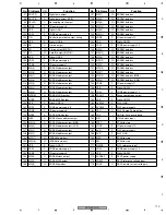
17
AVDAD0
P
ADC0 power supply
57
VDDI
P
CORE power supply 4
18
VRH0
I
ADC0 top reference electric potential
58
DVCK
I
DVIF clock input
19
VRL0
I
ADC0 bottom reference electric potential
59
VSS
P
Digital GND4
20
AVSAD0
P
ADC0 GND
60
RESETX
I
System reset input
21
AVDPG0
P
PGA0, CLP0, OFFC power supply
61
TEST0
I
Test mode setting 0
22
SYNCIN
I
ADC0 analog input
62
TEST1
I
Test mode setting 1
23
GIN
I
ADC0 analog input
63
AVDAD2
P
ADC2 power supply
24
CO0
O
PGA0 capacitor connection pin (REF0-synctip)
64
VRH2
I
ADC2 top reference electric potential
25
AVSPG0
P
PGA0, CLP0, OFFC GND
65
VRL2
I
ADC2 bottom reference electric potential
26
ATST0
I
Analog test pin
66
AVSAD2
P
ADC2 GND
27
AVSPG1
P
PGA1, CLP1, OFFC GND
67
AVDBF2
P
BUF2.CLP2 power supply
28
CO1
O
PGA1 capacitor connection pin (REF1-synctip)
68
CCRIN
I
ADC2 analog input
29
CVBSIN
I
ADC1 analog input
69
CO3
O
PGA3 capacitor connection pin
30
AVDPG1
P
PGA1, CLP1, OFFC power supply
70
CO2
O
BUF2 capacitor connection pin
31
AVSAD1
P
ADC1 GND
71
AVSBF2
P
BUF2, CLP2 GND
32
VRL1
I
ADC1 bottom reference electric potential
72
ATST1
I
Analog test pin
33
VRH1
I
ADC1 top reference electric potential
73
AVSBF3
P
BUF3, BUFF GND
34
AVDAD1
P
ADC1 power supply
74
CBIN
I
ADC3 analog input
35
VSS
P
Digital GND2
75
AVDBF3
P
BUF3.BUFF power supply
36
VDDI
P
CORE power supply 2
76
AVSAD3
P
ADC3 GND
37
VDDE
P
I/O power supply 2
77
VRL3
I
ADC3 bottom reference electric potential
38
CLK8
O
8fsc clock output for GCR
78
VRH3
I
ADC3 top reference electric potential
39
CLK4
O
4fsc clock output for GCR
79
AVDAD3
P
ADC3 power supply
40
GCLP
I/O
Clamp pulse output for GCR/FB input
80
VSS
P
Digital GND5
41
REQ
O
Interrupt signal output
81
VDDE
P
I/O power supply 4
42
VSS
P
Digital GND3
82
RX
O
--
43
VDDI
P
CORE power supply 3
83
SDATX
I/O
Data for serial communication (I2C: SDA)
44
VDDE
P
I/O power supply 3
84
SCL
I
Clock for serial communication (I2C: SCL)
45
AS
I
Address select input
85
XCS
I
--
46
SEL
I
Serial communication mode setting
86
VDDI
P
CORE power supply 5
47
DIN[9]
I
Digital data input (MSB)
87
VDDE
P
I/O power supply 5
48
DIN[8]
I
Digital data input
88
VSS
P
Digital GND6
49
DIN[7]
I
Digital data input
89
DOUT[9]
O
Digital data output (MSB)
50
DIN[6]
I
Digital data input
90
DOUT[8]
O
Digital data output
51
DIN[5]
I
Digital data input
91
DOUT[7]
O
Digital data output
52
DIN[4]
I
Digital data input
92
DOUT[6]
O
Digital data output
53
DIN[3]
I
Digital data input
93
DOUT[5]
O
Digital data output
54
DIN[2]
I
Digital data input
94
DOUT[4]
O
Digital data output
55
DIN[1]
I
Digital data input
95
DOUT[3]
O
Digital data output
56
DIN[0]
I
Digital data input (LSB)
96
DOUT[2]
O
Digital data output
Summary of Contents for DVR-531H-S
Page 17: ...DVR 533H S 17 5 6 7 8 5 6 7 8 C D F A B E ...
Page 41: ...DVR 533H S 41 5 6 7 8 5 6 7 8 C D F A B E I CN4501 To HDD CN9014 H 4 5 ...
Page 47: ...DVR 533H S 47 5 6 7 8 5 6 7 8 C D F A B E SIDE B SIDE B TUNB ASSY A A A CN101 VNP2004 A ...
Page 59: ...DVR 533H S 59 5 6 7 8 5 6 7 8 C D F A B E SIDE B SIDE B I I POWER SUPPLY UNIT I ...


