DVR-533H-S
107
5
6
7
8
5
6
7
8
C
D
F
A
B
E
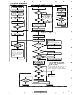
7.1.10 SETUP SEQUENCE
Tuner/FL microcomputer
System Codec IC (Initial Program Loader)
System Codec IC (Firmware)
DVD-R/RW Drive
Is ID check of drive OK?
Yes
Power ON ?
No
Yes
Has
command
arrived ?
Yes
OK
OK
FLASH check ?
NG
No
Stop
Tray Open
Yes
No
"CPRM ERR" displayed on FL display
Request for power off of
system-control computer made to
Tuner/FL microcomputer
System-control computer is turned off
(entering standby) following request
from Tuner/FL microcomputer
Obtaining LD
temperature data from drive.
Is temperature below
59
°
C?
No
Yes
Repair process
Is disc in?
Is starting/ID check of
HDD OK?
No
Yes
Is disc valid?
Yes
Repair required?
Yes
Yes
No
No
No
No
Playback
Playback
requested?
Yes
"HDD ERR" displayed on FL display
∗
1: If both the drive ID check and starting/ID
check of HDD failed, "CPRM ERR" is first
displayed on FL display.
*
Note:
The dictionary data for the HDD are stored on the
hard disk when the firmware is downloaded.
Therefore, when the HDD is replaced, be sure to
download the firmware.
Tuner/FL microcomputer starts up.
Connect the power cord.
System microcomputer starts up.
Downloading through
RS232C required.
"MONITOR" displayed
on the FL display.
Jumping to developed
firmware.
"POWER ON" displayed
on the FL display.
Key input and channel data
transmitted to the system
controller.
And make displayed data by
instructions from the system
controller, and switch a
channel.
LSI check ?
NG
"LSI NG" displayed
on the FL display.
Drive microcomputer
starts up.
ATA/ATAPI
command processing
Firmware stored in Flash memory
is developed in SD-RAM
expanding the compressed data.
Initialization of the peripheral
circuit register and RAM, etc.
Waiting for
communication to be
established.
Yes
No
Initialization of the
peripheral circuit
register and RAM, etc.
Initialization of the peripheral
circuit register and RAM, etc.
The version and content of
the dictionary data on the
hard disk are checked.*
"POWER ON" displayed
on the FL display.
Clock displayed
on the FL display.
Power ON/Release the reset
Communication start with the
Tuner/FL microcomputer.
∗
1
∗
1
Summary of Contents for DVR-531H-S
Page 17: ...DVR 533H S 17 5 6 7 8 5 6 7 8 C D F A B E ...
Page 41: ...DVR 533H S 41 5 6 7 8 5 6 7 8 C D F A B E I CN4501 To HDD CN9014 H 4 5 ...
Page 47: ...DVR 533H S 47 5 6 7 8 5 6 7 8 C D F A B E SIDE B SIDE B TUNB ASSY A A A CN101 VNP2004 A ...
Page 59: ...DVR 533H S 59 5 6 7 8 5 6 7 8 C D F A B E SIDE B SIDE B I I POWER SUPPLY UNIT I ...


