Chapter 4: Troubleshooting
Deko1000 & Deko550 Technical Reference And Service Guide
35
• Board 2 -- This would be the second TARGA card in workstations with more than one TARGA
card installed. This TARGA card is essentially the second channel. If you are facing the back
panel of the workstation and looking into the TARGA card bay area, then Board 2 would be the
second TARGA card from the left. (Refer to Figure 5-1 within the “Replacing Workstation Com-
ponents” section of Chapter 5 for TARGA card locations.)
• Board 3 -- This pull-down selection is not used because workstations configured for two chan-
nels will have a maximum of 2 TARGA cards installed.
• Board 4 -- This pull-down selection is not used because workstations configured for two chan-
nels will have a maximum of 2 TARGA cards installed.
4. Double click the test name that is to be run.
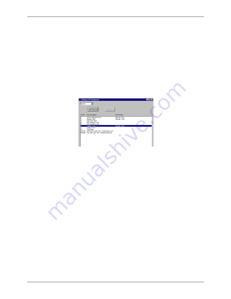
A single test can be performed by left-double clicking the name of the test. An example of
the manual testing window is shown in Figure 4-12.
Figure 4-12: Inflexion I/O Diagnostic manual testing window
Brief descriptions of the tests are as follows:
• 3210 Components Test -- This test checks that the various components on the TARGA card are
functioning in a normal manner.
Note:
Depending on the model of the TARGA card in your system, the “3210” indication may appear as a
different number.
• Memory Tests -- This test performs extensive memory testing on the TARGA card.
• Hub Clock Rate -- This is a test to check that the TARGA’s “clock” locks to the oscillator.
• SDI Channel Tests -- This test loops a signal out of the SDI portion of a channel and checks that
the signal comes back into the card exactly the same.
Important:
Loop back must be set up on the TARGA card to be tested. Refer to the “Setup
Before Testing” section above.
• Codec Tests -- This test checks the encoding and decoding ability of a Codec by putting a fixed
image through the Codec.
• Genlock Tests -- The NTSC and the PAL genlock tests both use a black burst or composite signal
as input source to Reference (REF) on the TARGA card. Either test locks the TARGA’s output
to the reference, and then tests to check if it is really locked to the reference output. The test then
checks that unlocking can occur.
Important:
An input black burst or composite input signal must be connected to the REF 1
connector on the back panel of the workstation if a genlock test is to be done. The input signal
format (i.e., NTSC or PAL) must match the format listed in the test name description.


