38
13.3.
Direct condensation schema
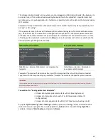
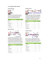
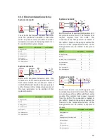
System schema 50
The external heat request requests the buffer
tank. The condenser is located in the buffer
tank. The pump as well as the flow and reflux
temperature sensors of the heat generator can
be omitted at this system schema.
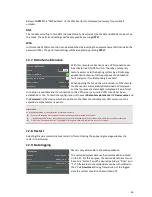
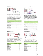
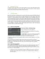
System schema 51
Buffer with integrated hot-water tank. This
scheme can also be used for a buffer tank with
fresh water module. The condenser is located
in the buffer tank. Therefore the pump as well
as the flow and reflux temperature sensors of
the heat generator can be omitted at this
system schematic.
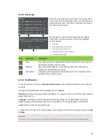
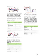
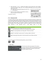
System schema 52
Each circuit has its own switching valve and it
may also have one for all. The external heat
request requests from the buffer. The
condenser of the heat generator is located in
the buffer. Therefore the pump as well as the
flow and reflux temperature sensors of the
heat generator can be omitted at this system
schema.
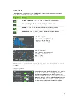
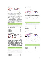
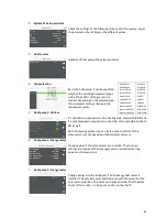
System schema 53
Each circuit has its own switching valve and
could also have one for all circuits. This scheme
can also be used for a buffer with fresh water
module. The external heat request requests
from the buffer. The condenser is located in
the buffer. Therefore the pump as well as the
flow and reflux temperature sensors of the
heat generator can be omitted at this system
schema.
Module
min. number
max. number
Heat generator
1
1
Buffer
1
1
Heating circuit
0
8
Hot water tank
0
4
Solar circuit
0
4
Ext. heat source
0
1
Ext. heat request
0
1
Module
min. number
max. number
Heat generator
1
1
Buffer
1
1
Heating circuit
0
8
Hot water tank
1
1
Solar circuit
0
4
Ext. heat source
0
1
Ext. heat request
0
1
Module
min. number
max. number
Heat generator
1
1
Buffer
1
1
Heating circuit / Cooling circuit
0
8
Hot water tank
0
4
Solar circuit
0
4
Ext. heat source
0
1
Ext. heat request
0
1
Module
min. number max. number
Heat generator
1
1
Buffer
1
1
Heating circuit / Cooling circuit
0
8
Hot water tank
1
1
Solar circuit
0
4
Ext. heat source
0
1
Ext. heat request
0
1

