33
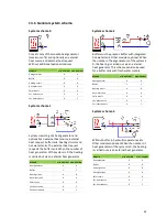
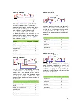
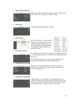
System schema 4
Buffer and hot-water tank must be present.
This scheme can also be used for a buffer tank
with fresh water module when a zone change
is available via a valve. Other modules
optional. When the number of heat generators
of the system is 0, the heating is carried out via
an external heat generator.
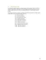
13.2.
Extended system schema
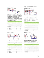
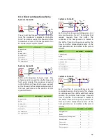
System schema 6
Heat pump cascade and a hot water tank.
Optionally with an external heat request and
an external heat source. The buffer tank with
optional heating circuits is loaded from a
collective flow. On a dedicated heat pump a
switch valve of the hot water tank is
connected.
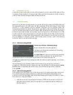
System schema 5
Heat generator and optionally an external heat
source, external heat request, an unmixed
heating circuit and optionally a hot water tank
connected via switching valve.
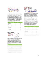
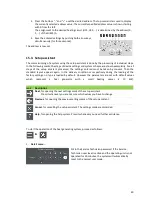
System schema 7
Each circuit has its own switching valve for
selection of a heat/cold generator. One
collective switching valve for all circuits. The
external heat request requests from buffer.
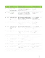
Module
min. number
max. number
Heat generator
0
4
Buffer
1
1
Heating circuit
0
8
Hot water tank
1
1
Solar circuit
0
4
Ext. heat source
0
1
Ext. heat request
0
1
Module
min. number
max. number
Heat generator
2
4
Buffer
0
2
Heating circuit
0
8
Hot water tank
1
1
Solar circuit
0
4
Ext. heat source
0
1
Ext. heat request
0
1
Module
min. number
max. number
Heat generator
0
4
Buffer
0
0
Heating circuit
0
1
Hot water tank
0
1
Solar circuit
0
4
Ext. heat source
0
1
Ext. heat request
0
1
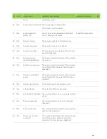
Module
min. number max. number
Heat generator
0
4
Buffer
1
1
Heating circuit / Cooling circuit
0
8
Hot water tank
1
4
Solar circuit
0
4
Ext. heat source
0
1
Ext. heat request
0
1

