background image

Digital Video Recorder User Manual 


119 


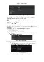
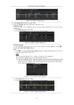
Figure 12. 6


PeanutHull Settings Interface 


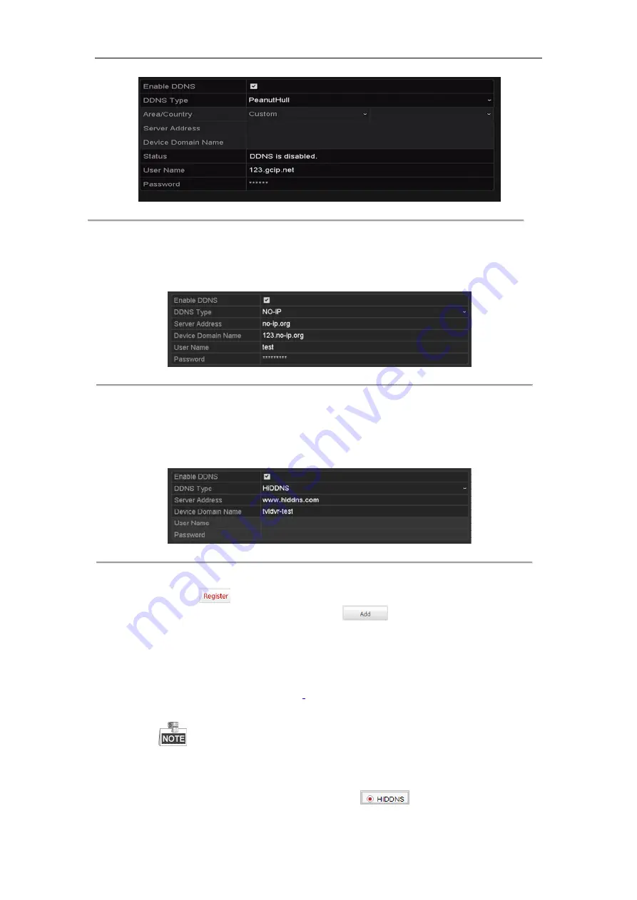
NO-IP:   

Enter the account information in the corresponding fields. Refer to the DynDNS settings. 
1)


Enter 

Server Address 

for NO-IP. 

2)


In the 

Device Domain Name

 text field, enter the domain obtained from the NO-IP website 

(www.no-ip.com).   

3)


Enter the 

User Name 

and 

Password 

registered in the NO-IP website. 


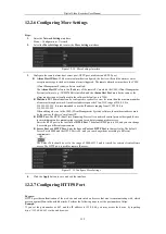
Figure 12. 7


NO-IP Settings Interface 


HiDDNS:   

1)


Select the continent/country of the server on which the device is registered.   

2)


Enter the 

Device Domain Name.

 You can use the alias you registered in the HiDDNS server or 

define a new device domain name. If a new alias of the device domain name is defined in the NVR, 
it will replace the old one registered on the server. You can register the alias of the device domain 
name in the HiDDNS server first and then enter the alias to the 

Device Domain Name

 in the NVR; 

you can also enter the domain name directly on the NVR to create a new one. 


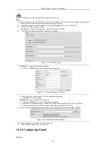
Figure 12. 8


HiDDNS Settings Interface 


Ø


Register the device on the HiDDNS server. 

1)


Go to the HiDDNS website: www.hiddns.com. 

2)


Click 

  to register an account if you do not have one and use the account to log in. 

3)


In the Device Management interface, click 

  to register the device. 

4)


Input 

Device Serial No.

Device Domain (Device Name)

 and 

HTTP Port

. And click 

OK

 to 

add the device. 

Ø


Access the Device via Web Browser or Client Software 

After having successfully registered the device on the HiDDNS server, you can access your device 
via web browser or Client Software with the 

Device Domain Name

 (

Device Name

). 

l


OPTION 1: Access the Device via Web Browser 

Open a web browser, and enter 

http://


www.hiddns.com/alias

 in the address bar. Alias refers to the 

Device Domain Name

 on the device or the

 Device Name 

on the HiDDNS server

.


Example:


http:// www.hiddns.com/nvr


If you mapped the HTTP port on your router and changed it to port No. except 80, you have to 
enter 

http:// www.hiddns.com/alias:HTTP port

 in the address bar to access the device. You can 

refer to 

Chapter 9.2.11

 for the mapped HTTP port No. 

l


OPTION 2: Access the devices via 

CMS


For NVMS7000, in the Add Device window, select 

  and then edit the device 

information. 

Summary of Contents for DVR-TVI-04

Page 1: ...Digital Video Recorder User Manual ...

Page 2: ...Disclaimer REGARDING TO THE PRODUCT WITH INTERNET ACCESS THE USE OF PRODUCT SHALL BE WHOLLY AT YOUR OWN RISKS OUR COMPANY SHALL NOT TAKE ANY RESPONSIBILITES FOR ABNORMAL OPERATION PRIVACY LEAKAGE OR OTHER DAMAGES RESULTING FROM CYBER ATTACK HACKER ATTACK VIRUS INSPECTION OR OTHER INTERNET SECURITY RISKS HOWEVER OUR COMPANY WILL PROVIDE TIMELY TECHNICAL SUPPORT IF REQUIRED SURVEILLANCE LAWS VARY BY...

Page 3: ...rference that may cause undesired operation EU Conformity Statement This product and if applicable the supplied accessories too are marked with CE and comply therefore with the applicable harmonized European standards listed under the EMC Directive 2004 108 EC the RoHS Directive 2011 65 EU 2012 19 EU WEEE directive Products marked with this symbol cannot be disposed of as unsorted municipal waste ...

Page 4: ...ty regulations of the nation and region Please refer to technical specifications for detailed information l Input voltage should meet both the SELV Safety Extra Low Voltage and the Limited Power Source with 100 to 240 VAC or 12 VDC according to the IEC60950 1 standard Please refer to technical specifications for detailed information l Do not connect several devices to one power adapter as adapter ...

Page 5: ... properly secured to a rack or shelf Major shocks or jolts to the unit as a result of dropping it may cause damage to the sensitive electronics within the unit Use the device in conjunction with an UPS if possible Power down the unit before connecting and disconnecting accessories and peripherals A factory recommended HDD should be used for this device Improper use or replacement of the battery ma...

Page 6: ... loss performance degradation or unexpected results Provides important points of the main text Digital Video Recorder User Manual 5 at may be found in this document are defined as follows Description Indicates a potentially hazardous situation which if not avoided could result in equipment damage data loss performance degradation or unexpected results Provides additional information to emphasize o...

Page 7: ...live view channel can be shielded l Motion detection video tampering detection video exception alarm video loss alarm and VCA alarm functions l Privacy mask l Several PTZ protocols supported PTZ preset patrol and pattern l Zooming in out by clicking the mouse and PTZ tracing by dragging mouse HDD Management l 1 SATA or 2 SATA hard disk can be connected l Each disk with a maximum of 6TB storage cap...

Page 8: ...nal video input recording resolution mismatch illegal login network disconnected IP confliction record exception HDD error and HDD full etc l Alarm triggers full screen monitoring audio alarm notifying surveillance center sending email and alarm output l VCA detection alarm line crossing detection and intrusion detection is supported l Support POS triggered alarm l Support coaxial alarm l Automati...

Page 9: ... and program upgrading l Remote system restart and shutdown l Support upgrading via remote FTP server l RS 485 transparent channel transmission l Alarm and exception information can be sent to the remote host l Remotely start stop recording l Remotely start stop alarm output l Remote PTZ control l Remote JPEG capture l Two way audio and voice broadcasting l Embedded WEB server Development Scalabil...

Page 10: ... 34 3 3 Channel Zero Encoding 36 3 4 Adjusting Live View Settings 37 3 5 Manual Video Quality Diagnostics 38 Chapter 4 PTZ Controls 39 4 1 Configuring PTZ Settings 40 4 2 Setting PTZ Presets Patrols and Patterns 41 4 2 1 Customizing Presets 41 4 2 2 Calling Presets 41 4 2 3 Customizing Patrols 42 4 2 4 Calling Patrols 43 4 2 5 Customizing Patterns 43 4 2 6 Calling Patterns 44 4 2 7 Customizing Lin...

Page 11: ...sion Detection 104 10 5 Region Entrance Detection 105 10 6 Region Exiting Detection 105 10 7 Loitering Detection 105 10 8 People Gathering Detection 106 10 9 Fast Moving Detection 106 10 10 Parking Detection 106 10 11 Unattended Baggage Detection 106 10 12 Object Removal Detection 107 10 13 Audio Exception Detection 107 10 14 Defocus Detection 108 10 15 PIR Alarm 108 Chapter 11 VCA Search 109 11 1...

Page 12: ...arameters 144 Chapter 15 DVR Management and Maintenance 145 15 1 Viewing System Information 146 15 2 Searching Log Files 146 15 3 Importing Exporting IP Camera Info 148 15 4 Importing Exporting Configuration Files 149 15 5 Upgrading System 150 15 5 1 Upgrading by Local Backup Device 150 15 5 2 Upgrading by FTP 150 15 6 Restoring Default Settings 151 Chapter 16 Others 152 16 1 Configuring General S...

Page 13: ...Digital Video Recorder User Manual 12 Chapter 1 Introduction ...

Page 14: ...TX RX indicator flickers green when network connection is functioning normally 2 USB Interfaces Universal Serial Bus USB ports for additional devices such as USB mouse and USB Hard Disk Drive HDD 3 Composite Keys 1 MENU Enter numeral 1 Access the main menu interface 2 ABC F1 Enter numeral 2 Enter letters ABC The F1 button when used in a list field will select all items in the list In PTZ Control m...

Page 15: ...ight is out Realize functions when the light is red 5 Control Buttons Directional buttons In menu mode the direction buttons are used to navigate between different fields and items and select setting parameters In playback mode the Up and Down buttons are used to speed up and slow down record playing and the Left and Right buttons are used to move the recording 30s forwards or backwards In the ima...

Page 16: ...by pressing and holding the button for 5 seconds 2 MENU Button Press the button to return to the main menu after successful login Press and hold the button for 5 seconds will turn off audible key beep In PTZ Control mode the MENU button will start wiper if applicable In Playback mode it is used to show hide the control interface 3 REC Button Enter the Manual Record setting menu In PTZ control sett...

Page 17: ...nu 10 PREV Button Switch between single screen and multi screen mode In PTZ Control mode it is used to adjust the focus in conjunction with the A FOCUS button Troubleshooting Remote Control Make sure you have install batteries properly in the remote control And you have to aim the remote control at the IR receiver in the front panel If there is no response after you press any button on the remote ...

Page 18: ...e list from your provider The operation of the mouse Table 1 3 Description of the Mouse Control Name Action Description Left Click Single Click Live view Select channel and show the quick set menu Menu Select and enter Double Click Live view Switch between single screen and multi screen Drag PTZ control Wheeling Privacy mask and motion detection Select target area Digital zoom in Drag and select t...

Page 19: ...e 1 3 Soft Keyboard Description of the buttons on the soft keyboard Table 1 4 Description of the Soft Keyboard Icons Icon Description Icon Description Number English letter Lowercase Uppercase Backspace Switch the keyboard Space Positioning the cursor Exit Symbols Reserved ...

Page 20: ...SB port for additional devices 5 HDMI HDMI video output connector 6 VGA DB15 connector for VGA output Display local video output and menu 7 AUDIO OUT RCA connector 8 Network Interface Connector for network 9 RS 485 Connector for RS 485 devices T and T pins connect to R and R pins of PTZ receiver respectively D D pin connects to Ta Tb pin of controller For cascading devices the first DVR s D D pin ...

Page 21: ...Digital Video Recorder User Manual 20 Chapter 2 Getting Started ...

Page 22: ... the power switch on the rear panel and the Power indicator LED should turn on indicating that the unit begins to start up 3 After startup the Power indicator LED remains on Shutting down the DVR Steps There are two proper ways to shut down the DVR To shut down the DVR Ÿ OPTION 1 Standard shutdown 1 Enter the Shutdown menu Menu Shutdown Figure 2 1 Shutdown Menu 2 Select the Shutdown button 3 Click...

Page 23: ... is allowed before activation You can also activate the device via Web Browser SADP or Client Software same password in the text field of Create New Password and Confirm New Password Figure 2 3 Settings Admin Password RECOMMENDED We highly recommend you create a strong password of your own choosing Using a minimum of 8 characters including at least three of the following categories upper case lett...

Page 24: ...ng the Setup Wizard 1 The Start Wizard can walk you through some important settings of the device If you don t want to use the Start Wizard at that moment click Exit You can also choose to use the Start Wizard next time by leaving the Start wizard when device starts checkbox checked 2 Click Next to enter the Password Configuration interface Enter the admin password If you want to change the passwo...

Page 25: ...tton after configuring the advanced network parameters which will take you to the HDD Management window shown in Figure 2 14 Figure 2 8 HDD Management 8 To initialize the HDD click the Init button Initialization will remove all the data saved in the HDD 9 Click Next to enter the IP Camera Management window 10 Add the IP camera 1 Click Search to search the online IP Camera The Security status shows...

Page 26: ...o activate the cameras in batch 2 Click the Add to add the camera 11 After finishing IP Camera settings click Next to enter the Record Settings window 12 Click the icon and you can enable the continuous recording or motion detection recording for all channels of the device 13 Click OK to complete the wizard settings ...

Page 27: ...he account will be locked for 60 seconds For the operator if you have entered the wrong password for 5 times the account will be locked for 60 seconds 2 4 4 User Logout Purpose After logging out the monitor turns to the live view mode and if you want to perform some operations you need to enter the user name and password to log in again Steps 1 Enter the Shutdown menu Menu Shutdown Figure 2 10 Log...

Page 28: ...line in the same network segment the Security status shows wh Figure 2 11 IP Camera Management Interface icon of the camera to enter the following interface to activate it You can also multiple cameras from the list and click the One touch Activate to activate the cameras in batch password of the camera to activate it hen you check the checkbox the camera s will be configured with the same VR If t...

Page 29: ...encoders with multiple channels only check the checkbox of Channel Port in the pop up window as shown in the following figure and click OK to add multiple channels Figure 2 13 Selecting Multiple Channels Ÿ OPTION 2 Steps 1 On the IP Camera Management interface click the Custom Adding button to pop up the Add IP Camera Custom interface 2 You can edit the IP address protocol management port and othe...

Page 30: ...ser Manual 29 Editing the Connected IP Cameras After the adding of the IP cameras the basic information of the camera is listed on the page you can configure the icon to edit the parameters You can edit the IP address protocol and other parameters If the connected device is an encoding device with multiple channels you can choose the channel to connect by selecting the channel port No in the dropd...

Page 31: ... are selectable Figure 2 16 Configure Signal Input Type 3 Click Apply to save the settings l Each two video channels are grouped in sequence e g CH01 and CH02 CH03 and CH04 and the two channels in the same group must be connected with the same type of video source i e the analog or HD TVI or AHD video input l In the live view interface when there is no video signal of the analog channel the corres...

Page 32: ...Digital Video Recorder User Manual 31 Chapter 3 Live View ...

Page 33: ...the live view mode there are icons at the right top of the screen for each channel showing the status of the record and alarm in the channel so that you can know whether the channel is recorded or whether there are alarms occur as soon as possible Table 3 1 Description of Live View Icons Icons Description Alarm video loss tampering motion detection or sensor alarm Record manual record schedule rec...

Page 34: ... 2 1 Using the Mouse in Live View You can refer to Table 3 3 for the description of mouse operation in live view mode Table 3 3 Mouse Operation in Live View Name Description Menu Enter the main menu of the system by right clicking the mouse Single Screen Switch to the single full screen by choosing channel number from the dropdown list Multi screen Adjust the screen layout by choosing from the dro...

Page 35: ...ect the Menu Output Mode under Menu Configuration General More Settings to Auto or HDMI VGA and then restart the device to switch the main output back to HDMI VGA output 3 2 3 Quick Setting Toolbar in Live View Mode On the screen of each channel there is a quick setting toolbar which shows when you click the screen Figure 3 3 Quick Setting Toolbar You can refer to Table 3 4 for the description of ...

Page 36: ...o Recorder User Manual 35 Figure 3 4 Digital Zoom Image Settings icon can be selected to enter the Image Settings menu You can drag the mouse or click adjust the image parameters including brightness contrast and saturation Refer to the Chapter 14 3 Figure 3 5 Image Settings ace Detection can be enabled if you click the icon The dialog pops up Click Yes and the full screen live ou can click to exi...

Page 37: ...ero encoding is supported as an option for you Steps 1 Enter the Live View Settings interface Menu Configuration Live View 2 Select the Channel Zero Encoding tab Figure 3 6 Live View Channel Zero Encoding 3 Check the checkbox after Enable Channel Zero Encoding 4 Configure the Frame Rate Max Bitrate Mode and Max Bitrate 5 Click the Apply button to activate the settings After you set the Channel Zer...

Page 38: ...abling auto switch in Live View Enable Audio Output Enables disables audio output for the selected camera in the live view mode Volume Adjust the volume of the audio output Event Output Designates the output to show event video If available you can select a different video output interface from the Video Output Interface when an event occurs Full Screen Monitoring Dwell Time The time in seconds to...

Page 39: ...ual Manual Video Quality Diagnostics Figure 3 9 Video Quality Diagnostics 2 Check the checkboxes to select the channels for diagnostics 3 Click the button Diagnose and the results will be displayed on a list You can view the video status and diagnostics time of the selected channels Figure 3 10 Diagnostics Result l Connect the camera to the device for the video quality diagnostics l Three exceptio...

Page 40: ...Digital Video Recorder User Manual 39 Chapter 4 PTZ Controls ...

Page 41: ...he PTZ Parameters button to set the PTZ parameters Figure 4 2 PTZ General 4 Select the parameters of the PTZ camera from the dropdown list All the parameters should be exactly the same as the PTZ camera parameters When the Coaxitron protocol is selected all the other parameters like the baud rate data bit stop bit parity and flow control are not configurable 5 Optional Click Copy button to copy th...

Page 42: ... 255 in the preset text field and click the Set button to link the location to the preset Repeat the steps from 2 to 3 to save more presets You can click the Clear button to clear the location information of the preset or click the Clear All button to clear the location information of all the presets 4 2 2 Calling Presets Purpose This feature enables the camera to point to a specified position suc...

Page 43: ...resets can be set following the steps above in Customizing Presets Steps 1 Enter the PTZ Control interface Menu Camera PTZ Figure 4 5 PTZ Settings 2 Select patrol No in the drop down list of patrol 3 Click the Set button to add key points for the patrol Figure 4 6 Key point Configuration 4 Configure key point parameters such as the key point No duration of staying for one key point and speed of pa...

Page 44: ... 1 Click the button PTZ in the lower right corner of the PTZ setting interface Or press the PTZ button on the front panel or click the PTZ Control icon in the quick setting bar or select the PTZ option in the right click menu to show the PTZ control panel 2 Click the General tab to show the general settings of the PTZ control Figure 4 7 PTZ Panel General 3 Select a patrol in the dropdown list and ...

Page 45: ... PTZ setting interface Or press the PTZ button on the front panel or click the PTZ Control icon in the quick setting bar or select the PTZ option in the right click menu to show the PTZ control panel 2 Click the General tab to show the general settings of the PTZ control Figure 4 9 PTZ Panel General 3 Click the Call Pattern button to call it 4 Click the Stop Pattern button to stop calling it 4 2 7...

Page 46: ...eps 1 Click the button PTZ in the lower right corner of the PTZ setting interface Or press the PTZ button on the front panel or click the PTZ Control icon in the quick setting bar to enter the PTZ setting menu in live view mode 2 Click the One touch tab to show the one touch function of the PTZ control Figure 4 11 PTZ Panel One touch 3 Click Linear Scan button to start the linear scan and click th...

Page 47: ...ere are 3 one touch park types selectable Click the corresponding button to activate the park action Park Quick Patrol The dome starts patrol from the predefined preset 1 to preset 32 in order after the park time The undefined preset will be skipped Park Patrol 1 The dome starts moving according to the predefined patrol 1 path after the park time Park Preset 1 The dome moves to the predefined pres...

Page 48: ...ettings interface In PTZ control mode the PTZ panel will be displayed when a mouse is connected with the device If no mouse is connected the icon appears in the lower left corner of the window indicating that this camera is in PTZ control mode Figure 4 13 PTZ Control Panel You can refer to Table 4 1 for the description of the PTZ panel icons Table 4 1 Description of the PTZ panel icons Icon Descri...

Page 49: ...Digital Video Recorder User Manual 48 Chapter 5 Recording Settings ...

Page 50: ...ct a camera from the camera dropdown list 3 Configure the following parameters for the Main Stream Continuous and the Main Stream Event Stream Type Set the stream type to be Video or Video Audio Resolution Set recording at resolution Bitrate Type Set the bitrate type to be Variable or Constant Video Quality Set the video quality of recording with 6 levels configurable The Stream Type Resolution Bi...

Page 51: ...ndant record means you save the record in the redundant HDD See Chapter 5 8 Configuring Redundant Recording Record Audio Enable this feature to record the sound and disable it to record the video without sound Video Stream Main stream and sub stream are selectable for recording When you select sub stream you can record for a longer time with the same storage space Enable 960 Mode The option is sup...

Page 52: ... 5 5 Sub stream Encoding 2 Select a camera in the camera dropdown list 3 Configure the parameters 4 Click Apply to save the settings 5 Optional If the parameters can also be used to other cameras click Copy to copy the settings to other channels ...

Page 53: ...s are marked in different color icons Continous scheduled recording Event recording triggered by all event triggered alarm Motion recording triggered by motion detection Alarm recording triggered by alarm M A recording triggered by either motion detection or alarm M A recording triggered by motion detection and alarm 2 Choose the camera you want to configure in the Camera dropdown list 3 Check the...

Page 54: ...ording for other days in the week If the schedule can also be set to other days click Copy Figure 5 9 Copy Schedule to Other Days The Holiday option is available when you enable holiday schedule in Holiday settings See Chapter 5 8 Configuring Holiday Record 5 Click OK to save setting and back to upper level menu Draw the schedule 1 Click on the color icon to select a record type in the event list ...

Page 55: ...tection 1 Choose camera you want to configure 2 Check the checkbox after Enable Motion Detection 3 Drag and draw the area for motion detection by mouse If you want to set the motion detection for all the area shot by the camera click Full Screen To clear the motion detection area click Clear Figure 5 12 Motion Detection Mask 4 Click the and the message box for channel information pops up Figure 5 ...

Page 56: ...losed for alarm type 3 Check the checkbox of Setting 4 Click the button 5 Choose the alarm triggered recording channel 6 Check the checkbox to select channel 7 Click Apply to save settings 8 Click OK to back to the upper level menu Repeat the steps from 1 to 8 to configure other alarm input parameters If the setting can also be applied to other alarm inputs click Copy and choose the alarm input nu...

Page 57: ... and defocus detection Steps 1 Enter the VCA settings interface and select a camera for the VCA settings Menu Camera VCA Figure 5 14 VCA Settings 2 Configure the detection rules for VCA events For details see the step 6 in Chapter 9 3 Line Crossing Detection 3 Click the icon to configure the alarm linkage actions for the VCA events Select Trigger Channel tab and select one or more channels which w...

Page 58: ...he Manual Record interface Menu Manual Figure 5 15 Manual Record 2 Enable manual record Click the status icon before camera number to change it to Or click the status icon of Analog to enable manual record of all channels 3 Disable manual record Click the status icon to change it to Or click the status icon of Analog to disable manual record of all channels After rebooting all the manual records e...

Page 59: ...ick OK to exit the Edit interface 4 Configure the record schedule Please refer to the Chapter 5 2 Configuring Record Schedule dropdown list or you can draw the schedule on the timeline of Holiday Digital Video Recorder User Manual 58 Configuring Holiday Recording schedule on holiday for that year You may want to have different plan for Enter the Record setting interface Figure 5 16 Holiday Setting...

Page 60: ...ime periods cannot be overlapped each other l In the time table of the channel both holiday schedule and normal day schedule are displayed l Repeat the above step 4 to set Holiday schedule for other channels If the holiday schedule can also be used to other channels click Copy and choose the channel you want to apply the settings ...

Page 61: ...ttings 3 Click OK to back to the upper level menu 3 Enter the Record setting interface Menu Record Parameters 1 Select the Record tab Digital Video Recorder User Manual 60 Configuring Redundant Recording means saving the record files not only in the R W HDD but also in the the data safety and reliability You must set the Storage mode in the HDD advanced settings to Group before you set the HDD pro...

Page 62: ...coding Parameters 2 Select Camera you want to configure 3 Check the checkbox of Redundant Record 4 Click Apply to save settings If the encoding parameters can also be used to other channels click Copy and choose the channel you want to apply the settings ...

Page 63: ...k Apply to save settings After you have configured the HDD groups you can configure the Recording settings following the procedure provided in Chapter 5 2 5 7 Digital Video Recorder User Manual 62 Configuring HDD Group Ds and save the record files in certain HDD group whether the storage mode of the HDD is Group If not set it to Group For detailed information Managing HDD Group to enter editing in...

Page 64: ...tart time and end time 4 Click Search to show the results Figure 5 24 Export Search Result 5 Protect the record files 1 Find the record files you want to protect and then click the icon which will turn to indicating that the file is locked The record files of which the recording is still not completed cannot be locked 2 Click to change it to to unlock the file and the file is not protected Protect...

Page 65: ...he recording will be stopped Digital Video Recorder User Manual 64 Figure 5 25 HDD General the HDD you want to protect Figure 5 26 HDD General Editing to save settings and back to the upper level menu save any files in a Read only HDD If you want to save files in the HDD change the property and is set to Read only the DVR cannot record any files Only live view mode is only when the DVR is saving f...

Page 66: ...dvanced interface Figure 5 27 Advanced Interface 3 Check the checkbox of 1080 Efficient Mode and click Apply to pop up the attention box 4 Click Yes to reboot the device to have new settings taken effect Task2 Disabling the 1080P Efficient Mode Steps 1 Enter the Record menu Menu Record 2 Click Advanced to enter the advanced interface 3 Uncheck the checkbox of 1080 Lite Mode and click Apply The fol...

Page 67: ...Digital Video Recorder User Manual 66 Chapter 6 Playback ...

Page 68: ...k Record Files Instant Playback Play back the recorded video files of a specific channel in the live view mode Channel switch is supported Choose a channel in live view mode and click the button in the quick setting toolbar In the instant playback mode only record files recorded during the last five minutes on this channel will be played Figure 6 1 Instant Playback Interface Playing Back by Normal...

Page 69: ...layback of multiple channels Figure 6 4 Toolbar of Playback Table 6 1 Detailed Explanation of Playback Toolbar Button Operation Button Operation Button Operation Audio on Mute Start Stop clipping Save clip s Add default tag Add customized tag Tag management Digital Zoom Smart Search Pause Reverse play Single frame reverse play Stop Pause play Play Single frame play 30s reverse 30s forward Speed do...

Page 70: ...art of Playback interface can be used to control playing process Pre play and post play can be configured for the playback of event triggered record files Pre play The time you set to play back before the event For example when an alarm triggered the recording at 10 00 if you set the pre play time as 5 seconds the video plays back from 9 59 55 Post play The time you set to play back after the even...

Page 71: ...ton to select the previous or next tag Please refer to Table 6 1 for the description of buttons on the toolbar 6 1 5 Playing Back by Smart Search Purpose The smart playback function provides an easy way to get through the less effective information When you select the smart playback mode the system will analyze the video containing the motion or VCA information mark it with green color and play it...

Page 72: ...he descriptions of the buttons on the Smart Playback Toolbar Table 6 2 Detailed Explanation of Smart Playback Toolbar Button Operation Button Operation Button Operation Draw line for the line crossing detection Draw quadrilateral for the intrusion detection Draw rectangle for the intrusion detection Set full screen for motion detection Clear all Start Stop clipping File management for video clips ...

Page 73: ...related video Max 8 4 2 1 are selectable Pre play and post play is not available for the motion event type 7 Click to search and play the matched video files 8 Optional You can click to filter the searched video files by setting the target characters including the gender and age of the human and whether he she wears glasses Figure 6 11 Set Result Filter The Result Filter function is supported by t...

Page 74: ...type and click Search button Figure 6 13 Result of System Log Search 3 Choose a log with record file and click button to enter Playback interface If there is no record file at the time point of the log the message box No result found will pop up 4 Playback management The toolbar in the bottom part of Playback interface can be used to control playing process ...

Page 75: ...enter the Sub periods Playback interface 3 Select a date and start playing the video file 4 Select the Split screen Number from the dropdown list Up to 16 screens are configurable Figure 6 15 Interface of Sub periods Playback According to the defined number of split screens the video files on the selected date can be divided into average segments for playback E g if there are video files existing ...

Page 76: ...face of External File Playback 6 2 Auxiliary Functions of Playback 6 2 1 Playing Back Frame by Frame Purpose Play video files frame by frame in order to check image details of the video when abnormal events happen Steps 1 Go to Playback interface and click button until the speed changes to Single frame 2 One click on the playback screen represents playback or adverse playback of one frame You can ...

Page 77: ...nnel Purpose You can play back record files of multi channel reversely Up to 16 ch simultaneous reverse playback is supported Steps 1 Enter Playback interface Menu Playback 2 Check more than one checkboxes to select multiple channels and click to select a date on the calendar Figure 6 18 4 ch Synchronous Playback Interface 3 Click to play back the record files reversely ...

Page 78: ...Digital Video Recorder User Manual 77 Chapter 7 Backup ...

Page 79: ...condition and click Search button to enter the search result interface Figure 7 1 Normal Video Search for Backup 4 The matched video files are displayed in Chart or List display mode Click to play the record file if you want to check it Check the checkbox before the video files you want to back up The size of the currently selected files is displayed in the lower left corner of the window Figure 7...

Page 80: ...ice Click OK to confirm Figure 7 4 Select File or Player for Backup 9 A prompt message will pop up after the backup process is complete Click OK to confirm Figure 7 5 Export Finished The backup of video files using USB writer or SATA writer has the same operating instructions Please refer to steps described above 7 1 2 Backing up by Event Search Purpose Back up event related record files using USB...

Page 81: ...g playback use buttons or in the playback toolbar to start or stop clipping record file s 3 Click the to enter the file management interface 4 Export the video clips in playback Please refer to step5 of Chapter 7 1 1 Backing up by Normal Video Search for details 7 2 Managing Backup Devices Management of USB flash drives USB HDDs and eSATA HDDs Steps 1 Enter the Export interface 2 Backup device man...

Page 82: ...Digital Video Recorder User Manual 81 Chapter 8 Alarm Settings ...

Page 83: ...to be the full screen and drag the sensitivity bar to set sensitivity Click to set alarm response actions Figure 8 2 Set Detection Area and Sensitivity 3 Click Trigger Channel tab and select one or more channels which will start to record or become full screen monitoring when motion alarm is triggered Figure 8 3 Set Trigger Camera of Motion Detection 4 Set arming schedule of the channel Select Arm...

Page 84: ... of motion alarm please refer to Chapter 8 7 Setting Alarm Response Actions Repeat the above steps to set up arming schedule of other days of a week Click the OK button to complete the motion detection settings of the channel 6 If you want to set motion detection for another channel repeat the above steps or just copy the above settings to it You are not allowed to copy the Trigger Channel action ...

Page 85: ...iguration 2 Set the handling method of the selected alarm input Check the Enable checkbox and click button to set its alarm response actions Figure 8 6 Alarm Input Settings Interface 3 Select Trigger Channel tab and select one or more channels which will start to record or become full screen monitoring when an external alarm input is triggered 4 Select Arming Schedule tab to set the channel s armi...

Page 86: ...chedule to other days 6 If necessary select PTZ Linking tab and set PTZ linkage of the alarm input Set PTZ linking parameters and click the OK button to complete the settings of the alarm input Please check whether the PTZ or speed dome supports PTZ linkage One alarm input can trigger presets patrol or pattern of more than one channel But presets patrols and patterns are exclusive Figure 8 8 Set P...

Page 87: ...Digital Video Recorder User Manual 86 Figure 8 9 Copy Settings of Alarm Input ...

Page 88: ...l Select Arming Schedule tab to set the channel s arming schedule Choose one day of a week and up to eight time periods can be set within each day Or you can click the Copy button to copy the time period settings to other day s Time periods shall not be repeated or overlapped Figure 8 11 Set Arming Schedule of Video Loss Repeat the above steps to set arming schedule of other days of a week You can...

Page 89: ...Digital Video Recorder User Manual 88 Repeat the above steps to finish settings of other channels or click the Copy button copy the above settings to them ...

Page 90: ...f video tampering Set arming schedule and alarm response actions of the channel 1 Click Arming Schedule tab to set the arming schedule of response action 2 Choose one day of a week and up to eight time periods can be set within each day Time periods shall not be repeated or overlapped Figure 8 13 Set Arming Schedule of Video Tampering 3 Select Linkage Action tab to set alarm response actions of vi...

Page 91: ...l Video Recorder User Manual 90 Repeat the above steps to finish settings of other channels or click the Copy button copy the above settings to them 5 Click the Apply button to save and activate the settings ...

Page 92: ...ng the bar The higher the threshold you set the harder the exception will be detected 4 Click to set handling method of video quality diagnostics Set arming schedule and alarm response actions of the channel 1 Click Arming Schedule tab to set the arming schedule of response action 2 Choose one day of a week and up to eight time periods can be set within each day Time periods shall not be repeated ...

Page 93: ...g recorded files Steps 1 Enter Exceptions interface and handle various exceptions Menu Configuration Exceptions Figure 8 15 Exception Settings Interface 2 Check the checkbox of Enable Event Hint to display the Event Exception icon when an exceptional event occurs And click the icon to select the detailed event hint for display Click the icon appears in the live view interface and you can view the ...

Page 94: ...lance Center Sends an exception or alarm signal to remote alarm host when an event occurs The alarm host refers to the PC installed with Remote Client The alarm signal will be transmitted automatically at detection mode when remote alarm host is configured Please refer to Chapter 11 2 6 Configuring More Settings for details of alarm host configuration Send Email Send an email with alarm informatio...

Page 95: ...arm Output 3 Repeat the above steps to set arming schedule of other days of a week You can also click Copy button to copy an arming schedule to other days Click the OK button to complete the arming schedule setting of alarm output 4 Click the Apply button to save the settings ...

Page 96: ...Digital Video Recorder User Manual 95 Chapter 9 POS Configuration ...

Page 97: ...nd end line tag for the POS overlay characters and the case sensitive property of the characters Figure 9 1 Universal Protocol Settings 5 Select the connection mode to TPC UDP Multicast RS 232 USB RS 232 or Sniff and click Settings to configure the parameters for each connection mode l TCP Connection When using TCP connection the port must be set from 0 to 65535 and the port for each POS machine m...

Page 98: ...gs l RS 232 Connection Connect the DVR and the POS machine via RS 232 The RS 232 settings can be configured in Menu Configuration RS 232 The Usage must be set to Transparent Channel l Multicast Connection When connecting the DVR and the POS machine via Multicast protocol set the multicast address and port Figure 9 5 Multicast Settings l Sniff Connection Connect the DVR and the POS machine via Snif...

Page 99: ...he overlay time of the characters The value ranges 5 3600 sec 5 optional Check the checkbox to enable the POS Overlay in Live View 6 Select the font color for the characters Figure 9 7 Overlay Character Settings You can adjust the size and position of textbox on the preview screen of POS settings interface by dragging the frame 7 Click Apply to activate the settings 8 Optional You can click the Co...

Page 100: ...ration POS Overlay Channel 2 Click to select an analog or IP camera from the camera list on the right and then click a POS item from the POS list you want to overlay on the selected camera Click or to go to the previous or next page of cameras 3 You can also click to overlay all POS items to the first 8 channels in order And the is used to clear all POS overlay settings 4 Click the Apply button to...

Page 101: ...the channel Select Arming Schedule tab to set the channel s arming schedule Choose one day of a week and up to eight time periods can be set within each day Or you can click the Copy button to copy the time period settings to other day s Time periods shall not be repeated or overlapped 6 Click the Handling tab to set up alarm response actions of POS alarm please refer to Chapter 8 7 Setting Alarm ...

Page 102: ...Digital Video Recorder User Manual 101 Chapter 10 VCAAlarm ...

Page 103: ...ed instructions 5 Click the Rule Settings button to set the face detection rules You can drag the slider to set the detection sensitivity Sensitivity Range 1 5 The higher the value is the more easily the face can be detected Figure 10 1 Set Face Detection Sensitivity 6 Click Apply to activate the settings 10 2 Vehicle Detection Purpose Vehicle Detection is available for the road traffic monitoring...

Page 104: ...ossing detection alarm 6 Click the Rule Settings button to set the line crossing detection rules 1 Select the direction to A B A B or B A A B Only the arrow on the B side shows When an object goes across the configured line both directions can be detected and alarms are triggered A B Only the object crossing the configured line from the A side to the B side can be detected B A Only the object cros...

Page 105: ...tion area is longer than the set time the alarm will be triggered 2 Drag the slider to set the detection sensitivity Sensitivity Range 1 100 The value of the sensitivity defines the size of the object which can trigger the alarm The higher the value is the more easily the detection alarm can be triggered 3 Percentage Range 1 100 Percentage defines the ratio of the in region part of the object whic...

Page 106: ...ete drawing Only one region can be configured You can use the to clear the existing virtual line and re draw it Up to 4 rules can be configured 8 Click Apply to save the settings 10 6 Region Exiting Detection Purpose Region exiting detection function detects people vehicle or other objects which exit from a pre defined virtual region and some certain actions can be taken when the alarm is triggere...

Page 107: ... easily a moving object can trigger the alarm l Up to 4 rules can be configured 10 10 Parking Detection Purpose Parking detection function detects illegal parking in places such as highway one way street etc and a series of actions can be taken when the alarm is triggered l Please refer to the Chapter 9 4 Intrusion Detection for operating steps to configure the parking detection l The Threshold 5s...

Page 108: ...ction function detects the abnormal sounds in the surveillance scene such as the sudden increase decrease of the sound intensity and some certain actions can be taken when the alarm is triggered The audio exception detection is supported by all analog channels Steps 1 Enter the VCA settings interface Menu Camera VCA 2 Select the camera to configure the VCA You can click the checkbox of Save VCA Pi...

Page 109: ... configure the defocus detection l The Sensitivity in the Rule Settings ranges from 1 to 100 and the higher the value is the more easily the defocus image can trigger the alarm 10 15 PIR Alarm Purpose A PIR Passive Infrared alarm is triggered when an intruder moves within the detector s field of view The heat energy dissipated by a person or any other warm blooded creature such as dogs cats etc ca...

Page 110: ...Digital Video Recorder User Manual 109 Chapter 11 VCA Search ...

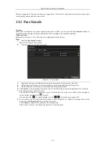
Page 111: ...ng the captured face pictures or video files 4 Upload the pictures from your local storage device for matching the detected face pictures 5 Set the similarity level for the source pictures and the captured pictures 6 Click Search to start searching The search results of face detection pictures are displayed in list or in chart 7 Play the face picture related video file You can double click on a fa...

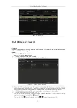
Page 112: ...he VCA detection type from the dropdown list including the line crossing detection intrusion detection unattended baggage detection object removal detection region entrance detection region exiting detection parking detection loitering detection people gathering detection and fast moving detection 5 Click Search to start searching The search results of pictures are displayed in list or in chart 6 ...

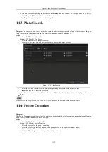
Page 113: ...ure 11 4 Plate Search 4 Select the country from the drop down list for searching the location of the vehicle plate 5 Input the plate No in the field for search 6 Click Search to start searching The search results of detected vehicle plate pictures are displayed in list or in chart Please refer to the Step7 Step8 of Section 10 1 Face Search for the operation of the search results 11 4 People Counti...

Page 114: ...Digital Video Recorder User Manual 113 Figure 11 5 People Counting Interface 6 You can click the Export button to export the statistics report in excel format ...

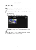
Page 115: ...ace Menu VCA Search Heat Map 2 Select the camera for the heat map processing 3 Select the report type to Daily Report Weekly Report Monthly Report or Annual Report 4 Set the statistics time Figure 11 6 Heat Map Interface 5 Click the Counting button to export the report data and start heat map statistics and the results are displayed in graphics marked in different colors As shown in Figure 10 8 re...

Page 116: ...Digital Video Recorder User Manual 115 Chapter 12 Network Settings ...

Page 117: ...nd then the system is connecting with the extranet the data will be forwarded through the default route Net fault Tolerance Mode The two NIC cards use the same IP address and you can select the Main NIC to LAN1 or LAN2 By this way in case of one NIC card failure the device will automatically enable the other standby NIC card so as to ensure the normal running of the whole system Load Balance Mode ...

Page 118: ...oot You can go to Menu Maintenance System Info Network interface to view the status of PPPoE connection 12 2 2Configuring PT Cloud Purpose PT Cloud provides the mobile phone application and as well the service platform page to access and manage your connected NVR which enables you to get a convenient remote access to the surveillance system Steps 1 Enter the Network Settings interface Menu Configu...

Page 119: ...ith your ISP is required before configuring the system to use DDNS Steps 1 Enter the Network Settings interface Menu Configuration Network 2 Select the DDNS tab to enter the DDNS Settings interface 3 Check the Enable DDNS checkbox to enable this feature 4 Select DDNS Type Six different DDNS types are selectable Default IPServer DynDNS PeanutHull NO IP and HiDDNS IPServer Input Server Address for I...

Page 120: ...S Settings Interface Ø Register the device on the HiDDNS server 1 Go to the HiDDNS website www hiddns com 2 Click to register an account if you do not have one and use the account to log in 3 In the Device Management interface click to register the device 4 Input Device Serial No Device Domain Device Name and HTTP Port And click OK to add the device Ø Access the Device via Web Browser or Client So...

Page 121: ...the Apply button to save and exit the interface The time synchronization interval can be set from 1 to 10080 minutes and the default value is 60 minutes If the DVR is connected to a public network you should use a NTP server that has a time synchronization function such as the server at the National Time Center IP Address 210 72 145 44 If the DVR is set in a more customized network NTP software ca...

Page 122: ...og box Steps 1 Click to activate the External Port Settings dialog box Configure the external port No for server port http port and RTSP port respectively l You can use the default port No or change it according to actual requirements l External Port indicates the port No for port mapping in the router l The value of the RTSP port No should be 554 or between 1024 and 65535 while the value of the o...

Page 123: ...55 255 255 When adding a device to the CMS Client Management System software the multicast address must be the same as the device s multicast IP l RTSP Port The RTSP Real Time Streaming Protocol is a network control protocol designed for use in entertainment and communications systems to control streaming media servers Enter the RTSP port in the text field of RTSP Port The default RTSP port is 554...

Page 124: ...igned certificate 1 Click the Create button to create the following dialog box Figure 12 17 Create Self signed Certificate 2 Enter the country host name IP validity and other information 3 Click OK to save the settings OPTION 2 Create the authorized certificate 1 Click the Create button to create the certificate request 2 Download the certificate request and submit it to the trusted certificate au...

Page 125: ... or host name e g smtp 263xmail com SMTP Port The SMTP port The default TCP IP port used for SMTP is 25 Enable SSL optional Click the checkbox to enable SSL if required by the SMTP server Sender The name of sender Sender s Address The Email address of sender Select Receivers Select the receiver Up to 3 receivers can be configured Receiver The name of the receiver of the Email Receiver s Address Th...

Page 126: ...Digital Video Recorder User Manual 125 Figure 12 20 Network Traffic Interface 2 You can view the sending rate and receiving rate information on the interface The traffic data is refreshed every 1 second ...

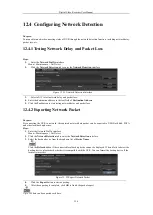
Page 127: ...d packet loss 12 4 2Exporting Network Packet Purpose By connecting the DVR to network the captured network data packet can be exported to USB flash disk SATA and other local backup devices Steps 1 Enter the Network Traffic interface Menu Maintenance Net Detect 2 Click the Network Detection tab to enter the Network Detection interface 3 Select the backup device from the dropdown list of Device Name...

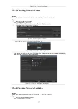
Page 128: ...nterface Figure 12 23 Checking Network Status If the network is normal the following message box pops out Figure 12 24 Network Status Checking Result If the message box pops out with other information instead of this one you can click Network button to show the quick setting interface of the network parameters Figure 12 25 Network Parameters Configuration 12 4 4Checking Network Statistics Purpose ...

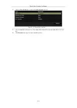
Page 129: ...work Stat tab to enter the Network Statistics interface Figure 12 26 Network Stat Interface 3 View the bandwidth of Remote Live View bandwidth of Remote Playback and bandwidth of Net Total Idle 4 Click Refresh button to get the latest bandwidth statistics ...

Page 130: ...Digital Video Recorder User Manual 129 Chapter 13 HDD Management ...

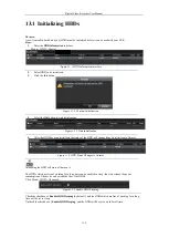
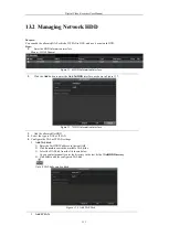
Page 131: ...ation 5 After the HDD has been initialized the status of the HDD will change from Uninitialized to Normal Figure 13 4 HDD Status Changes to Normal Initializing the HDD will erase all data on it The HDDs which are free of working for a long time can be enabled to sleep thus to decrease the power consumption of the device and extend the life of the HDDs Click Menu HDD Advanced Figure 13 5 Enable HDD...

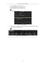
Page 132: ...as shown in Figure 13 7 Figure 13 7 HDD Information Interface 3 Add the allocated NetHDD 4 Select the type to NAS or IP SAN 5 Configure the NAS or IP SAN settings Add NAS disk 1 Enter the NetHDD IP address in the text field 2 Click Search to search the available NAS disks 3 Select the NAS disk from the list shown below Or you can just manually enter the directory in the text field of NetHDD Direct...

Page 133: ...ow 4 Click the OK button to add the selected IP SAN disk Up to 8 IP SAN disks can be added Figure 13 9 Add IP SAN Disk 5 After having successfully added the NAS or IP SAN disk return to the HDD Information menu The added NetHDD will be displayed in the list If the added NetHDD is uninitialized please select it and click the Init button for initialization Figure 13 10 Initialize Added NetHDD ...

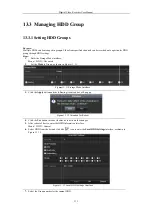
Page 134: ...Figure 13 13 7 Select the Group number for the current HDD Digital Video Recorder User Manual 133 Managing HDD Group Setting HDD Groups Multiple HDDs can be managed in groups Video from specified channels can be recorded onto a particular HDD to Group as shown in Figure 13 11 Figure 13 11 Storage Mode Interface button and the following Attention box will pop up Figure 13 12 Attention for Reboot bu...

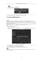
Page 135: ...perty Digital Video Recorder User Manual 134 lt group No for each HDD is 1 confirm the settings Figure 13 14 Confirm HDD Group Settings up Attention box click the Yes button to finish the settings Property redundancy read only or read write R W Before setting the HDD property please set the storage mode to Group refer to step1 4 of Chapter 13 3 1 Setting HDD Groups important recorded files from be...

Page 136: ...the storage capacity in the text field of Max Record Capacity GB 5 You can copy the quota settings of the current camera to other cameras if required Click the Copy button to enter the Copy Camera interface as shown in Figure 13 17 Figure 13 17 Copy Settings to Other Camera s 6 Select the camera s to be configured with the same quota settings You can also click the checkbox of Analog to select all...

Page 137: ...schedule Back to enter the record interface choose a certain camera from the Camera dropdown list and check the Enable Schedule checkbox to enable the schedule recording For detailed recording schedule refer to 5 2 Configuring Recording Schedule This POS recording is supported by some DVRs only 8 Upload the event triggered recording files to the cloud storage 1 Back to enter the cloud storage inte...

Page 138: ...isplayed on the list as shown in Figure 13 19 Figure 13 19 View HDD Status 1 If the status of HDD is Normal or Sleeping it works normally If the status is Uninitialized or Abnormal please initialize the HDD before use And if the HDD initialization is failed please replace it with a new one Checking HDD Status in System Information Interface Steps 1 Enter the System Information interface Menu Maint...

Page 139: ...pes of anticipating failures Steps 1 Enter the HDD Detect interface Menu Maintenance HDD Detect 2 Click the S M A R T Settings tab to enter the interface 3 Select the HDD to view its S M A R T information list as shown in Figure 13 21 If you want to use the HDD even when the S M A R T checking is failed you can check the checkbox before the Continue to use this disk when self evaluation is failed ...

Page 140: ...nu HDD HDD Detect 2 Click the Bad Sector Detection tab to enter the interface 3 Select a HDD and click the Detect button to start detecting Figure 13 22 Bad Sector Detecting 4 You can click the Pause button to pause the detection and click the Resume button to resume the detection 5 If there is error information about the HDD you can click the Error Info button to view the information ...

Page 141: ... Type to HDD Error from the dropdown list 3 Check the checkbox s below to select the linkage action s for HDD error as shown in Figure 12 22 The linkage actions can be selected to Audible Warning Notify Surveillance Center Send Email and Trigger Alarm Output Figure 13 23 Configure HDD Error Alarm 4 When the Trigger Alarm Output is selected you can also select the alarm output to be triggered from ...

Page 142: ...Digital Video Recorder User Manual 141 Chapter 14 Camera Settings ...

Page 143: ...lay Mode and the OSD font Figure 14 1 OSD Configuration Interface 6 You can use the mouse to drag the text frame on the preview window to adjust the OSD position 7 Copy Camera Settings 1 If you want to copy the OSD settings of the current camera to other cameras click the Copy button to enter the Copy Camera interface as shown in Figure 14 2 Figure 14 2 Copy Settings to Other Cameras 2 Select the ...

Page 144: ...4 Use the mouse to draw a zone on the window The zones will be marked with different frame colors Up to 4 privacy mask zones can be configured and the size of each area can be adjusted 5 The configured privacy mask zones on the window can be cleared by clicking the corresponding Clear Zone1 4 icons on the right side of the window or click Clear All to clear all zones Figure 14 4 Set Privacy Mask A...

Page 145: ...ds cannot be overlapped with each other 4 Select the mode from the drop down list of Mode there are four modes selectable for the analog cameras Standard Indoor Dim Light and Outdoor 5 Adjust the image parameters according to actual needs The parameters include Brightness Contrast Saturation Hue Sharpness and Denoising for the analog cameras You can also click Restore to set the parameters to the ...

Page 146: ...Digital Video Recorder User Manual 145 Chapter 15 DVR Management and Maintenance ...

Page 147: ...available for the DVR without Alarm l You can view the hardware version in the Device Information interface 15 2 Searching Log Files Purpose The operation alarm exception and information of the DVR can be stored in log files which can be viewed and exported at any time Steps 1 Enter the Log Search interface Menu Maintenance Log Information Figure 15 2 Log Search Interface 2 Set the log search cond...

Page 148: ... the log files click the Export button to enter the Export menu as shown in Figure 14 5 Figure 15 4 Export Log Files 7 Select the backup device from the dropdown list of Device Name 8 Click the Export to export the log files to the selected backup device You can click the New Folder button to create new folder in the backup device or click the Format button to format the backup device before log e...

Page 149: ... or deleting the content and copy the setting to other devices by importing the excel file to it Steps 1 Enter the camera management interface Menu Camera Camera Click the IP Camera Import Export tab the content of detected plugged external device appears 2 Click the Export button to export configuration files to the selected local backup device 3 To import a configuration file select the file fro...

Page 150: ...red with the same parameters Steps 1 Enter the Import Export Configuration File interface Menu Maintenance Import Export 2 Click the Export button to export configuration files to the selected local backup device 3 To import a configuration file select the file from the selected backup device and click the Import button After the import process is completed you must reboot the DVR After having fin...

Page 151: ...m the backup device 5 Click the Upgrade button to start upgrading 6 After the upgrading is complete reboot the DVR to activate the new firmware 15 5 2Upgrading by FTP Before you start Configure PC running FTP server and DVR to the same Local Area Network Run the 3rd party TFTP software on the PC and copy the firmware into the root directory of TFTP Steps 1 Enter the Upgrade interface Menu Maintena...

Page 152: ...ll parameters except the network including IP address subnet mask gateway MTU NIC working mode default route server port etc and user account parameters to the factory default settings Factory Defaults Restore all parameters to the factory default settings Restore to Inactive Restore the device to the inactive status 3 Click the OK button to restore the default settings The device will reboot auto...

Page 153: ...Digital Video Recorder User Manual 152 Chapter 16 Others ...

Page 154: ...Select the CVBS output standard to NTSC or PAL which must be the same with the video input standard Resolution Select the output resolution which must be the same with the resolution of the VGA HDMI display Time Zone Select the time zone Date Format Select the date format System Date Select the system date System Time Select the system time Mouse Pointer Speed Set the speed of mouse pointer 4 leve...

Page 155: ...er the General Settings interface Menu Configuration General 2 Choose DST Settings tab Figure 16 2 DST Settings Interface You can check the checkbox before the Auto DST Adjustment item Or you can manually check the Enable DST checkbox and then you choose the date of the DST period ...

Page 156: ...mber of DVR The Device No can be set in the range of 1 255 and the default No is 255 CVBS Output Brightness Adjust the video output brightness via the CVBS interface Auto Logout Set timeout time for menu inactivity E g when the timeout time is set to 5 Minutes then the system will exit from the current operation menu to live view screen after 5 minutes of menu inactivity Menu Output Mode You can c...

Page 157: ...d interface Figure 16 4 User Management Interface Add User interface Figure 16 5 Add User Menu Enter the information for new user including User Name Password Confirm Level and User s MAC Set the password for the user account PASSWORD RECOMMENDED We highly recommend you create a strong password of your own choosing using a minimum of 8 characters including upper case letters lower case letters num...

Page 158: ...abling and disabling analog camera s Adding deleting and editing of network camera s This function is supported by HDVR series Local Advanced Operation Operating HDD management initializing HDD setting HDD property upgrading system firmware Local Shutdown Reboot Shutting down or rebooting the device Remote Configuration Remote Log Search Remotely viewing logs that are saved on the device Remote Pa...

Page 159: ...s Local PTZ Control Locally controlling PTZ movement of the selected camera s Remote PTZ Control Remotely controlling PTZ movement of the selected camera s Local Video Export Locally exporting recorded files of the selected camera s Local Camera Management is provided for the IP cameras only 3 Click OK to save the settings and exit 16 4 2Deleting a User Steps 1 Enter the User Management interface ...

Page 160: ...dress Change Password if you want to change the password and input the new Password and Confirm A strong password is recommended e password and MAC address Check the checkbox of Change Password if you want to change the password and the input the correct old password and the new password in the Confirm PASSWORD RECOMMENDED We highly recommend you create a strong password of your own choosing using...

Page 161: ...Digital Video Recorder User Manual 160 Chapter 17 Appendix ...

Page 162: ...transceiver modem over Ethernet and in plain Metro Ethernet networks DDNS Dynamic DNS is a method protocol or network service that provides the capability for a networked device such as a router or computer system using the Internet Protocol Suite to notify a domain name server to change in real time ad hoc the active DNS configuration of its configured hostnames addresses or other information sto...

Page 163: ...rther process Ÿ There is a beep sound after a new bought device starts up Possible Reasons a No HDD is installed in the device b The installed HDD has not been initialized c The installed HDD is not compatible with the device or is broken down Steps 1 Verify at least one HDD is installed in the device 1 If not please install the compatible HDD Please refer to the Quick Operation Guide for the HDD ...

Page 164: ...tuck when DVR is playing back by single or multi channel cameras Possible Reasons a The frame rate is not the real time frame rate b The DVR supports up to 16 channel synchronize playback at the resolution of 4CIF if you want a 16 channel synchronize playback at the resolution of 720p the frame extracting may occur which leads to a slight stuck Steps 1 Verify the frame rate is real time frame rate...

Page 165: ...elect Menu HDD General to view the HDD status and verify the HDD is detected and can be read and written normally 4 Check if the fault is solved by the above steps If it is solved finish the process If not please contact the engineer from our company to do the further process ...

Reviews: