phytron
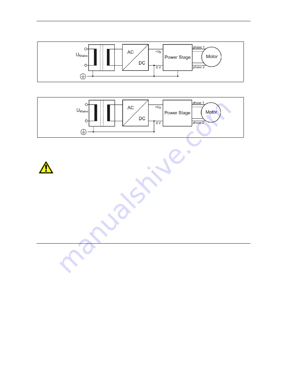
If there is no PE clamp on the motor, the 0 V wire
must
be grounded to complete the
protective measure PELV (Fig. 13 and Fig.14):
Fig. 13: PELV – Grounding: 0 V and Power Stage
Fig. 14: PELV – Grounding: 0 V
Protective measure PELV for application of the +U
B
should not exceed 70 V
DC
or
50 V
AC
at dry environment (environmental conditions 3 acc. to IEC 61201).
The supply transformer must be constructed with reinforced or double
insulation between supply and secondary winding (acc. to EN 61558).
Only use motors which are checked acc. to EN 60034-1 (500 V
AC
/1 minute).
3.4 Putting into Service
3.4.1 For Rotary Switch Mode
Please follow the described order when you put into service the MCD power stage:
1. Connect the MCD acc. to protective measure in chap. 3.3.
2. Wire the
17-pole Phönix connector
(MC1,5/(17-ST-3,5)) with the required
leads and connect it to the MCD (See fig. 2: male connector of the MCD
(MC1,5/17-G-3,5)).
3. Connect the
motor
to the MCD. Use the Phönix connector called: IC2,5/4-ST-5,08.
The equivalent male connector (IC2,5/4-G-5,08) is on the front panel of the MCD.
Please note chapter 6.1 to 6.4.
4. Setting switch positions for
Rotary switch mode
For rotary switch setting see table in chapter 8.
17
MA 2102-A005 GB
•
Set the rotary switch I
Run
to the required run current. The phase current should
not exceed the maximum admissible motor current.


