Programming Your Application
6-2
650G AC Drive
MMI Parameters Table
MMI Parameters Table
Display
Parameter
Description
Range
Default
SET::PAR Menu
APPLICATION
This parameter selects and loads the Application to
be used. APP 0 will not control a motor. APP 6, 7 &
8 are for future use. You can edit an Application in
DSE and, then set this parameter to CUSTOM to
produce your own custom Application.
Refer to the 650G Software Product Manual,
Chapter 5: "Applications" which gives detailed
information about each Application.
Note:
Parameter values are changed to
factory settings by loading a new
Application, except Motor Parameters
(indicated
M
)
0= NULL
1= STANDARD
2= LOCAL/REM
(AUTO/MANUAL)
3= PRESETS
4= RAISE/LOWER
5= PID
6= APP 6
7= APP 7
8= APP 8
9= CUSTOM
1
MAX SPEED
M
The frequency at which the 650G will run when
maximum setpoint is applied. The default is
Product Code dependent
7.5 to 300Hz
50 or
60Hz
MIN SPEED
The minimum frequency at which the 650G will
run, as a percentage of the MAX SPEED parameter
-100.0 to 100.0%
0.0%
ACCEL TIME
The time taken for the 650G output frequency to
ramp up from zero to MAX SPEED
0.0 to 3000.0s
10.0s
DECEL TIME
The time taken for the 650G output frequency to
ramp down from MAX SPEED to zero
0.0 to 3000.0s
10.0s
MOTOR
CURRENT
M
This parameter contains the motor nameplate full-
load line current
0.01 to 999.99A
product
code
dependent
BASE
FREQUENCY
M
The output frequency at which maximum voltage is
reached. The default is Product Code dependent
7.5 to 240Hz
50 or
60Hz
JOG SETPOINT
Speed the 650G will run at if the Jog input is high,
as a percentage of the MAX SPEED parameter
-100.0 to 100.0%
10.0%
RUN STOP MODE RAMPED : The motor speed is reduced to zero at a
rate set by DECEL TIME (
P
5). A 2 second DC pulse
is applied at end of ramp
COAST : The motor is allowed to freewheel to a
standstill
DC INJECTION : On a stop command, the motor
volts are rapidly reduced at constant frequency to
deflux the motor. A low frequency braking current
is then applied until the motor speed is almost
zero. This is followed by a timed DC pulse to hold
the motor shaft.
0=RAMPED
1=COAST
2=DC INJECTION
0
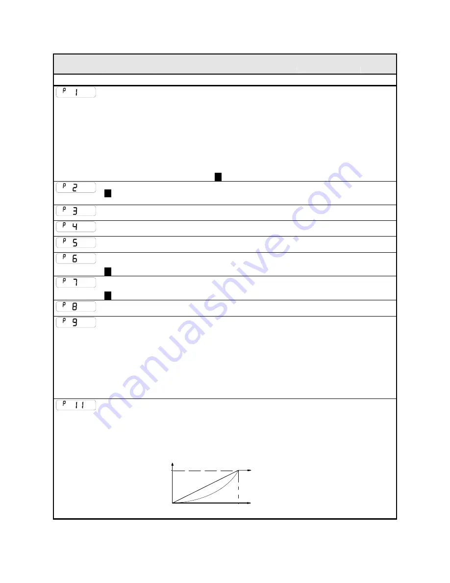
V/F SHAPE
LINEAR LAW: This gives a constant flux
characteristic up to the BASE FREQUENCY
FAN LAW: This gives a quadratic flux characteristic
up to the BASE FREQUENCY. This matches the
load requirement for fan and most pump
applications
Refer to
P
12
LINEAR
FREQUENCY
= BASE FREQUENCY
100%
CONSTANT
POWER RANGE
OUTPUT VOLTS
f B
f B
QUADRATIC LAW
0=LINEAR LAW
1=FAN LAW
0
www.comoso.com


