D-64
Programming
DC590+ Series DC Digital Drive
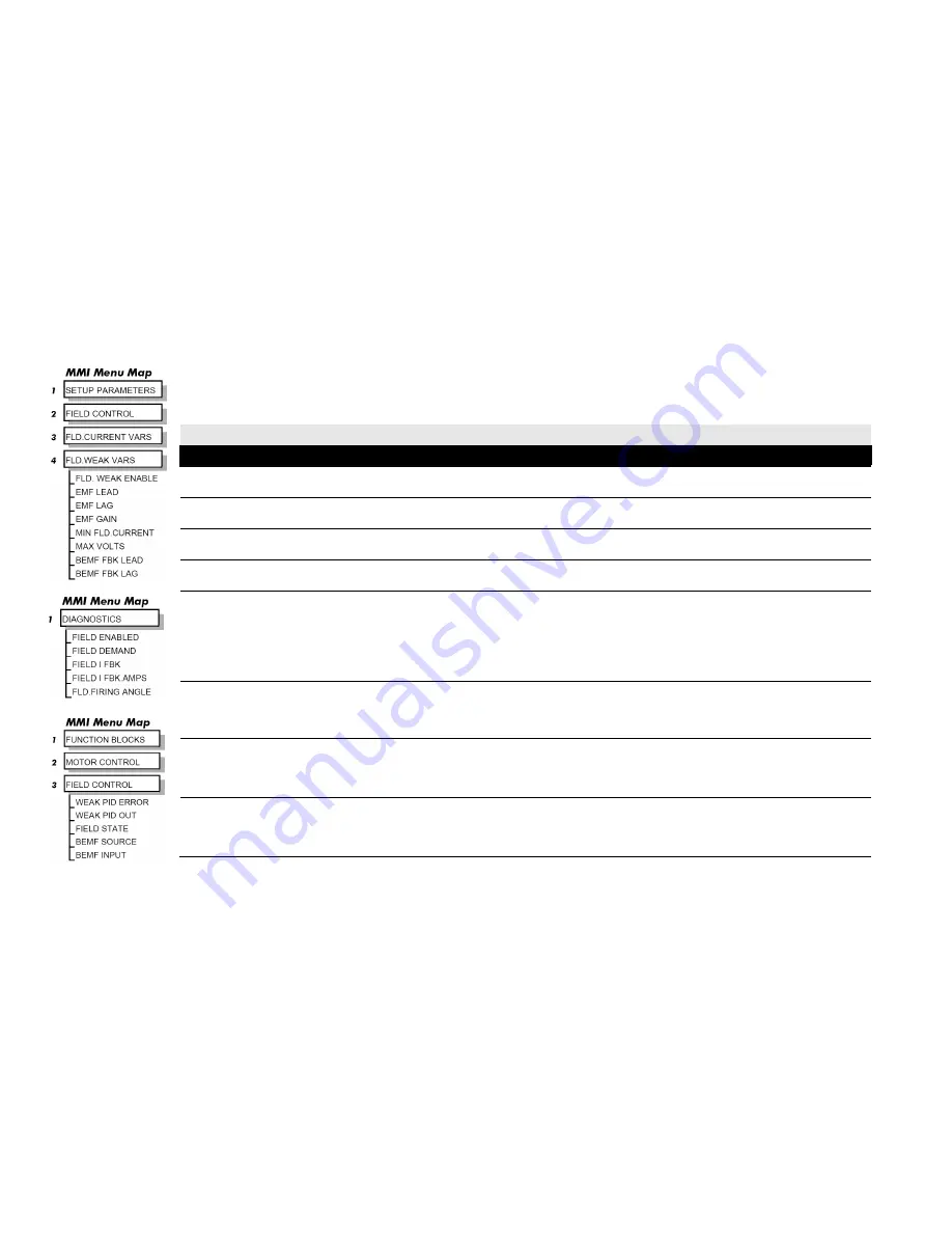
FLD WEAK VARS : MMI Sub-Menu
In certain applications of a DC motor controller, high speeds can only be achieved by reducing the field current and therefore the resultant torque. This
is termed as the Constant-Horsepower region or Field-Weakening region, and the speed at which it begins is known as the Base Speed.
FIELD CONTROL
Parameter
Tag
Range
FIELD ENABLE
170
DISABLED / ENABLED
Enables and disables the drive motor Field Control.
SETPOINT
171
0.00 to 100.00 %
Field current setpoint as percentage of calibrated value.
PROP. GAIN
173
0.00 to 100.00
This is the proportional gain adjustment of the field current PI loop. The default of 0.10 is equivalent to a real gain of 10.
INT. GAIN
172
0.00 to 100.00
This is the integral gain adjustment of the field current PI loop.
FLD. WEAK ENABLE
174
DISABLED/STANDARD/ADVANCED
Activates the additional motor back-emf, gain-limited PI loop for field weakening (field spillover) control.
STANDARD mode uses the control loop to convert the back-emf in excess of the MAX VOLTS setting, into a reduction of the demanded field
current.
ADVANCED mode also adds in a feedforward control term, based on a comparison of the speed feedback to the calculated base speed,
and uses adaptive gain, in both the back-emf and speed control loops, to compensate for the gain effects of reduced field operation.
EMF LEAD
175
0.10 to 50.00
With field weakening control enabled, a gain-limited PI loop is brought into operation. This is the lead time constant adjustment of the field
weakening PI loop. With a default of 2.00, real time constant = 200ms.
Refer to Chapter 5: "Control Loops" for details of Tuning.
EMF LAG
176
0.00 to 200.00
This is the lag time constant adjustment of the field weakening PI loop
With a default of 40.00, real time constant = 4000ms.
Refer to Chapter 5: "Control Loops" for details of Tuning.
EMF GAIN
177
0.00 to 100.00
This is the steady-state gain adjustment of the field weakening PI loop.
With a default of 0.30, real gain = 30.
Refer to Chapter 5: "Control Loops" for details of Tuning.
Summary of Contents for 590+ series
Page 2: ......
Page 14: ...Cont 12...
Page 16: ...DC590 Series DC Digital Drive...
Page 20: ......
Page 32: ...2 12 Product Overview DC590 Series DC Digital Drive...
Page 34: ......
Page 130: ...3 96 Installing the Drive DC590 Series DC Digital Drive...
Page 132: ......
Page 164: ...4 32 Operating the Drive DC590 Series DC Digital Drive...
Page 166: ......
Page 174: ...5 8 Control Loops DC590 Series DC Digital Drive...
Page 176: ......
Page 202: ......
Page 222: ...7 20 Trips and Fault Finding DC590 Series DC Digital Drive...
Page 224: ......
Page 242: ......
Page 272: ...DC590 Series DC Digital Drive...
Page 288: ...B 16 Certification DC590 Series DC Digital Drive...
Page 290: ......
Page 342: ...C 52 Parameter Specification Tables DC590 Series DC Digital Drive...
Page 344: ......
Page 365: ...Programming D 21 DC590 Series DC Digital Drive Functional Description...
Page 494: ...D 150 Programming DC590 Series DC Digital Drive Programming Block Diagram Sheet 1...
Page 495: ...Programming D 151 DC590 Series DC Digital Drive Programming Block Diagram Sheet 2...
Page 496: ...D 152 Programming DC590 Series DC Digital Drive Programming Block Diagram Sheet 3...
Page 497: ...Programming D 153 DC590 Series DC Digital Drive Programming Block Diagram Sheet 4...
Page 502: ...D 158 Programming DC590 Series DC Digital Drive...
Page 504: ......
Page 506: ...E 2 Technical Specifications DC590 Series DC Digital Drive...
Page 507: ...Technical Specifications E 3 DC590 Series DC Digital Drive...


