Connection
OMCTT5639E09
30
5.6 Connecting with external device connecting unit
5.6.1 Applications
5.6.2 Connection
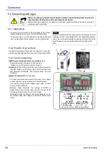
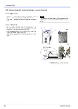
• Draw harnesses or cables from the connecting unit via
this wire port
(d)
. (*Loosen four crews
(a)
and two eye
-
bolts
(b)
and then remove the top panel
(c)
.
• To enable the function of the connecting unit, make sure
to turn ON the DIP switch DSW2 #10.
(When not using the function of communication, turn it off
again.)
To switch the pages of stored welding conditions by connect
-
ing external equipment (sequencer) to the product.
(For details, see manual of the external device connecting
unit.)
Note
For preventing troubles caused by incorporation of the
high frequency wave, see “Installation: Peripheral equip
-
ment”.
a
b
c
Front
Rear
e
d
200 V harness
(*)
Line from the
connecting unit
e
(*)
: [
CN1
] is for an external device.
Summary of Contents for YC-300BP2YAF
Page 10: ...Rated Specifications OMCTT5639E09 10 2 2 1 Dimensions ...
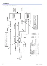
Page 16: ...Installation OMCTT5639E09 16 Example of extension cable connection ...
Page 49: ...Parts list OMCTT5639E09 49 9 Parts list ...
Page 52: ...OMCTT5639E09 52 ...
Page 53: ...Circuit diagram OMCTT5639E09 53 10 Circuit diagram NF9 NF8 ...
Page 54: ...Circuit diagram OMCTT5639E09 54 10 1 Enlarged left half NF8 MCB ...
Page 55: ...Circuit diagram OMCTT5639E09 55 10 2 Enlarged right half NF9 ...
Page 62: ...OMCTT5639E09 62 ...
Page 63: ...OMCTT5639E09 63 ...

