Introduction
OMCTT5639E09
2
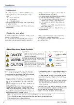
Signal Words and Safety Symbols
Disclaimer
Panasonic Smart Factory Solutions Co., Ltd. (hereinafter
called “PSFS”) and its affiliates (including any subcontrac
-
tor, sales company or agent) shall not assume or undertake
any responsibility or liability of the followings:
•
Any problem arising out of, or directly or indirectly attributable to,
the failure of user to carry out those
normal installation, normal
maintenance, normal adjustment and periodical check of this
Product.
• Any problem arising out of any Force Majeure, including but not
limited to, act of God.
• Any malfunction or defect of this Product that is directly or indi
-
rectly the result of any malfunction or defect of one or more
related parts or products that are not supplied by PSFS. Or any
problem arising out of, or directly or indirectly attributable to, the
combination of this Product with any other product, equipment,
devices or software that is not supplied by PSFS.
• Any problem arising out of, or directly or indirectly attributable to,
user’s failure to strictly carry out or follow all of the conditions
and instructions contained in this instruction manual, or user’s
misusage, mishandle, operational miss or abnormal operation.
• Any problem arising out of this Product or the use of it, the
cause of which is other than the foregoing but is also not attrib
-
utable to PSFS.
• Any claim of a third party that this Product infringes the intellec
-
tual property rights of such third party that are directly or indi
-
rectly caused by User’s use of this Product and relate to the
method of production.
ANY LOST PROFITS OR SPECIAL, INDIRECT, INCIDEN
-
TAL OR CONSEQUENTIAL DAMAGES IN CONNECTION
WITH OR ARISING FROM ANY MALFUNCTION,
DEFECT OR OTHER PROBLEM OF THIS PRODUCT.
Signal Words
Safety Symbols (Examples)
Indicates an imminently hazardous situ-
ation which, if not avoided, will result in
death or serious injury.
Indicates a prohibited
action.
Indicates a potentially hazardous situa
-
tion which, if not avoided, could result in
death or serious injury.
Indicates a
mandatory action.
Indicates a potentially hazardous situa
-
tion which, if not avoided, could result in
minor injury or property damage.
Indicates a
hazard alert.
DANGER
WARNING
CAUTION
This operating instructions manual is based on the information as of November, 2020.
The information in this operating instructions manual is subject to change without notice.
English version is the original instructions.
Introduction
• This product is useful up to 400Hz in AC TIG frequency.
• It is easy to use even with multiple functions incorpo
-
rated.
(a) “Simple touch panel”
(b) “Digital display”
(c) “LCD display screen”
• As it is fully digitalized, it has the excellent reproducibility
of welding conditions.
• It can store and reproduce up to 50 different welding con
-
ditions in total.
• Using an external connecting unit (option) enables it to
call its stored conditions more easily.
• An IT system can also be introduced into your welding
site by enhancing communication facilities.
(a) It can be connected to the controller “G2” of our
industrial robot “Panasonic robots VR2 series”.
(b) It can also be connected to other various open
networks*.
*: Networks constructed by using standard proto
-
cols, such as TCP/IP, etc.
• Compact and lightweight / mass: 51kg (69% of our con
-
ventional machine)
Caution for your safety
Read and understand this manual before installing, operat
-
ing or servicing this product.
This equipment and instructions are for use only by per
-
sons trained and experienced in the safety operation of
welding equipment. Do not allow untrained persons to
install, operate, or maintain this equipment.
The wiring and grounding should be done by educated
and/or skilled person.
Summary of Contents for YC-300BP2YAF
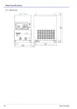
Page 10: ...Rated Specifications OMCTT5639E09 10 2 2 1 Dimensions ...
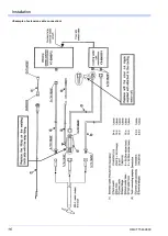
Page 16: ...Installation OMCTT5639E09 16 Example of extension cable connection ...
Page 49: ...Parts list OMCTT5639E09 49 9 Parts list ...
Page 52: ...OMCTT5639E09 52 ...
Page 53: ...Circuit diagram OMCTT5639E09 53 10 Circuit diagram NF9 NF8 ...
Page 54: ...Circuit diagram OMCTT5639E09 54 10 1 Enlarged left half NF8 MCB ...
Page 55: ...Circuit diagram OMCTT5639E09 55 10 2 Enlarged right half NF9 ...
Page 62: ...OMCTT5639E09 62 ...
Page 63: ...OMCTT5639E09 63 ...

