Operation
OMCTT5639E09
31
6. Operation
6.1 Preparation steps
6.1.1 Use of protective equipment
6.1.2 Confirmation of completed connection
Check to confirm the following connections
- Connections to input power unit and grounding wire.
- Connections to base metal, welding torch and of gas.
(See sections “Configuration” and “Connection.”
6.1.3 Turning ON power
DANGER
To protect you and other people from gases, fumes and lack of oxygen that may
be generated during the welding operation, make sure to prepare ventilation facil
-
ities and use protective equipment, etc.
• Welding operations in narrow spaces may cause asphyxia due to lack of oxygen.
• Prepare ventilation facilities to prevent the inhalation of gases and fumes generated during the welding
operation. Otherwise, wear a respirator.
CAUTION
To protect you and other people from arc light, fly
-
ing spatters, slag, and arc noises generated by
welding, use protective equipment.
• Wear leather gloves and safety shoes to protect the exposed parts of your
eyes and skin.
• Prepare light-shielding glasses or a welding face-shield with a light-shield
-
ing filter plate appropriate to the applied welding current.
• Prepare the ear protection device.
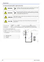
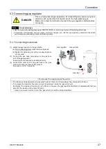
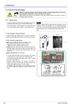
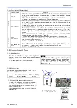
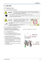
(1) Turn on the switch of the distribution box.
(2) Turn on the “POWER” switch. (The set-value display
and the LCD display on the front panel are turned on.)
6.1.4 Adjusting gas flow rate
(1) Place the “GAS” switch to the “PURGE” position.
(2) Open the main valve of the gas cylinder. (Make sure
that the flow adjustment knob is at the side of [SHUT]
before opening the main switch.)
(3) Turn the flow adjustment knob in the direction of
[OPEN], and adjust it until the flow meter indicates the
required value.
(4) On completion of the flow rate, set the “GAS” switch
to the “WELD” position.
“GAS” switch
“POWER” switch
Gas cylinder
Flow adjustment knob
main valve
Summary of Contents for YC-300BP2YAF
Page 10: ...Rated Specifications OMCTT5639E09 10 2 2 1 Dimensions ...
Page 16: ...Installation OMCTT5639E09 16 Example of extension cable connection ...
Page 49: ...Parts list OMCTT5639E09 49 9 Parts list ...
Page 52: ...OMCTT5639E09 52 ...
Page 53: ...Circuit diagram OMCTT5639E09 53 10 Circuit diagram NF9 NF8 ...
Page 54: ...Circuit diagram OMCTT5639E09 54 10 1 Enlarged left half NF8 MCB ...
Page 55: ...Circuit diagram OMCTT5639E09 55 10 2 Enlarged right half NF9 ...
Page 62: ...OMCTT5639E09 62 ...
Page 63: ...OMCTT5639E09 63 ...


