Names and Functions
OMCTT5639E09
20
4.1.3 Switches and rear side
DANGER
When removing or replacing a fuse:
To prevent an accident caused by an electric shock, make sure to
turn the power switch off before such removal or replacement
CAUTION
About power switch:
• When the power switch is turned off automatically, do not turn it on again. (Consult
with sales distributor of Panasonic representatives.)
• When activating a power generator, turn off the power switch.
1
2
3
4
5
7
6
Front panel
8
9
10
11
12
13
Rear panel
1
“Power” switch (NFB)
Turns the power supply on and off.
Turn it on and off from outside of the case.
The lever position at the time of tripping (means
that the switch is turned off automatically due to
over-current) is same as the off position.
2
Gas supply switch
Normally set it to the “welding” side. When
checking the gas flow rate, set it to the “inspec
-
tion” side.
3
Gas outlet joint
4
Negative (-) terminal (fingertip joint)
5
(+) Terminal (fingertip joint)
6
Torch switch outlet
7
Outlet for remote control unit
Insert the plug of a remote control unit (optional
item), and it is securely fixed.
8
Input power cables
(with PE): The PE cable is
connected to the PE terminal in the power distri
-
bution box.
9
Wiring port
(with grommet)
for the communication connector
10
Wiring port
(with grommet)
for the jig terminal
11
3A power fuse (FU1)
This is a fuse for the control power circuit.
This fuse is resistant to rush current.
12
Cooling fan air-outlet:
This is the cooling fan air-
outlet to cool this product.
Do not leave any obstacles near this outlet.
13
Gas inlet joint
(Screw size: U9 / 16 Thread 18):
Connect the welding shield gas from the gas reg
-
ulator securely.
Any gas incorporation may affect the result of
welding.
Summary of Contents for YC-300BP2YAF
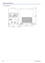
Page 10: ...Rated Specifications OMCTT5639E09 10 2 2 1 Dimensions ...
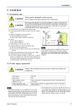
Page 16: ...Installation OMCTT5639E09 16 Example of extension cable connection ...
Page 49: ...Parts list OMCTT5639E09 49 9 Parts list ...
Page 52: ...OMCTT5639E09 52 ...
Page 53: ...Circuit diagram OMCTT5639E09 53 10 Circuit diagram NF9 NF8 ...
Page 54: ...Circuit diagram OMCTT5639E09 54 10 1 Enlarged left half NF8 MCB ...
Page 55: ...Circuit diagram OMCTT5639E09 55 10 2 Enlarged right half NF9 ...
Page 62: ...OMCTT5639E09 62 ...
Page 63: ...OMCTT5639E09 63 ...

