Connection
OMCTT5639E09
29
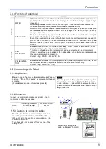
5.4.4 Functions of jig terminal
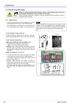
5.5 Connecting with Robot
5.5.1 Applications
5.5.2 Connection
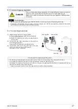
Connect the communication cable from a robot to the D-
Sub connector
(d)
on the rear panel.
Terminal names
Function
IN
P
U
T
WATER
• When the circuit is opened between these terminals, the operation of this product is sus
-
pended.(Such suspension results in the stoppage of the welding output, gas supply and gas
inspection.)
• When using the water-cooling torch, connect a signal for reduced-water-level detection, etc.
• To release such suspension, close the circuit between these terminals.
EMERGENCY
• When the circuit is closed between these terminals, the emergency stop function of this prod
-
uct is activated.(Such suspension results in the stoppage of the welding output, gas supply
and gas inspection.)
• To release this emergency top, close the circuit between these terminals after turning the
power switch off, and then turn it on again.
• Even if the power switch is turned on with the circuit between these terminals opened, this
product does not operate. Close the circuit between these terminals, and then turn the power
switch on again. (In other words, turn the power on with the circuit between these terminals
closed.)
O
U
T
P
U
T
CUR.
DETECTION
• Between these terminals, the normally-open relay contact (contact a) is connected, and it is
closed at all times while output current* is detected.
*: Initial current, welding current (pulse current and base current) and then crater current.
• If there is something to be operated at the jig side while such output current is detected, use
these terminals for such an operation.
• Contact rating: 100VAC 0.5A, 24VDC 2A
PULSE DETEC
-
TION
• Between these terminals, the normally-open contact (contact a) of a photo MOS relay is con
-
nected, and it is closed in synchronization with the pulse output current only.
• Contact rating: 100VAC/DC 0.13A
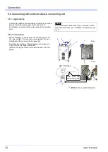
•
Robot:
In case of perform welding operation using Panaso
-
nic robots “VR-2 or TA-G2 series” by connecting to the robot
controller.
(For details, see manuals of individual products.)
Note
Keep the signal lines from a jig and/or a robot away from
the welding arc area, the welding torch, the base-mate
-
rial-side cable, etc. to prevent troubles caused by incor
-
poration of the high frequency wave. And keep the wiring
length within 10m.
Connecting connector
DIP switch (DSW1)
Robot
RS-422(CN22)
(d)
#6: ON
5.5.3 Cautions at connecting cables
• To enable the function of communication, make sure
to turn the power off, and then set the DIP switch.
(When not using the function of communication, turn
off the DIP switch #6.)
• Turn the switch
(e)
on and off from on top of the
orange cover.
a
b
c
e
d
(Shown DSW settings are
factory settings at shipment.)
Summary of Contents for YC-300BP2YAF
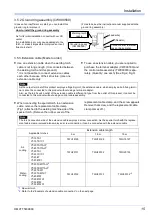
Page 10: ...Rated Specifications OMCTT5639E09 10 2 2 1 Dimensions ...
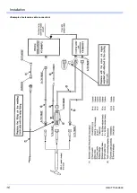
Page 16: ...Installation OMCTT5639E09 16 Example of extension cable connection ...
Page 49: ...Parts list OMCTT5639E09 49 9 Parts list ...
Page 52: ...OMCTT5639E09 52 ...
Page 53: ...Circuit diagram OMCTT5639E09 53 10 Circuit diagram NF9 NF8 ...
Page 54: ...Circuit diagram OMCTT5639E09 54 10 1 Enlarged left half NF8 MCB ...
Page 55: ...Circuit diagram OMCTT5639E09 55 10 2 Enlarged right half NF9 ...
Page 62: ...OMCTT5639E09 62 ...
Page 63: ...OMCTT5639E09 63 ...

