background image

Names and Functions

OMCTT5639E09

18

4. Names and Functions

4.1 Front panel

4.1.1 Data display/setting section and welding conditions selecting section

For  details  of  functions,  see  “Welding  conditions”  in  this

chapter.”

*1

: In the case of a welding voltage, indicates the welding

voltage (between output terminals of this product) during

the welding operation rather than the set value.

*2

: See section “Operation” for how to display welding volt

-

age.

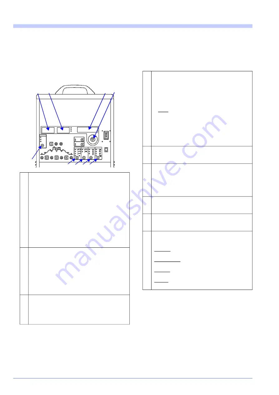
1

Digital ammeter

 • Indicates welding current values during the weld

-

ing.  (Displays  an  average  current  value  mea

-

sured  during  the  period  of  0.4  second  in

amperes.) 

Due  to  a  rounding  error,  a  resulting  value  may

vary within the range of plus or minus 1A.

As this ammeter is designed to display an aver

-

age current value measured during the period of

0.4 second, it may not be able to follow the varia

-

tion of current  quickly  enough when  the current

changes frequently during the pulse welding, etc.

 • Indicates an “Err” (error) mark in case of a trou

-

ble.

2

Set-value display

 • Indicates the set values

*

1

 of current (A), time (S),

frequency (Hz), pulse width (%), AC balance (%),
DC ratio (%), welding voltage (V)

*

2

, etc.

 • The unit display lamp changes according to the

type of indicated set values.

 • Indicates  an  “Err”  (error)  number  in  case  of  a

trouble.

3

LCD display

 • This is the information display area.
 • Indicates condition-setting items in letters.
 • Indicates  error  contents  in  letters  in  case  of  a

trouble.

1

2

3

4

5

7 8 9

6

4

Jog dial

 • This is a dial to carry out the function of a potenti

-

ometer (setup of current and time).

For example, to set welding current to 125A, turn

the  dial  to  the  right  (increase)  or  to  the  left

(decrease) until such a value is indicated (on the

set-value display).

Note: Turning the jog dial without discretion may

result  in  the  change  of  a set  value  for the item

currently indicated on the LCD display.

 • Use the press button function of the jog dial in the

following situation.

In the reproduction, storage or details mode (See

item 9 in the right column.)

5

“Weld conditions” selection button

Selects a required welding method (DC TIG, AC 

TIG or MIX TIG).

6

“Crater control” selection button

Regarding the selected welding method, selects 

the “absence, presence or repeat” of the crater 

control, as well as the “spot” (arc spot welding).

The arc spot welding can be done only in the case 

of “DC TIG” and “AC TIG” welding.

7

“Pulse” selection button

Regarding the selected welding method, selects 

the absence or presence” of pulses.

8

“AC waveform” selection button

In case the AC welding method is selected, selects 

an AC waveform (standard, hard or soft).

9

“Mote” selection button

Selects an operation “mode” of this product (weld

-

ing, reproduction, storage, or details).

Welding: Can be used to set welding conditions 

and conduct a welding operation.

Reproduction: Can be used to reproduce stored 

welding conditions. 

Storage: Can be used to store the present welding 

condition. 

Details: Can be used to change the factory-set 

mode of this product. 

Summary of Contents for YC-300BP2YAF

Page 1: ...tructions carefully and save this manual for future use First of all please read Safety precautions or Safety manual 2011 Operating Instructions Model No YC 300BP2YAF Fully digital controlled power source OMCTT5639E09 Inverter TIG welding power source ...

Page 2: ...HIS PRODUCT Signal Words Safety Symbols Examples Indicates an imminently hazardous situ ation which if not avoided will result in death or serious injury Indicates a prohibited action Indicates a potentially hazardous situa tion which if not avoided could result in death or serious injury Indicates a mandatory action Indicates a potentially hazardous situa tion which if not avoided could result in...

Page 3: ...compatible this may require additional protection measures h The time of day that welding or other activities are to be carried out 3 The user shall be observe to reduce emission distur bance as below a Welding equipment should be connected to mains supply according to the manufacture s recommen dations b Welding equipment should be routinely maintained according to the manufacture s recommendatio...

Page 4: ...ищує 0 1wt ваги речовини або в концентрації до 1000 частин на мільйон 2 кадмій Cd не перевищує 0 01wt ваги речовини або в концентрації до 100 частин на мільйон 3 ртуть Hg не перевищує 0 1wt ваги речовини або в концентрації до 1000 частин на мільйон 4 шестивалентний хром Cr6 не перевищує 0 1wt ваги речовини або в концентрації до 1000 частин на мільйон 5 полібромбіфеноли PBB не перевищує 0 1 ваги ре...

Page 5: ...nnection 29 5 5 3 Cautions at connecting cables 29 5 6 Connecting with external device connect ing unit 30 5 6 1 Applications 30 5 6 2 Connection 30 6 Operation 31 6 1 Preparation steps 31 6 1 1 Use of protective equipment 31 6 1 2 Confirmation of completed connection 31 6 1 3 Turning ON power 31 6 1 4 Adjusting gas flow rate 31 6 2 Steps after welding operation 32 6 2 1 Shutting off Gas 32 6 2 2 ...

Page 6: ...fined area or above floor level check related national state and local codes and regulations for any special treatment and comply with it if any Electromagnetic disturbance 1 Pacemaker wearers should consult their doctor before going near arc welding Magnetic fields can affect pacemakers 2 Peripheral electronics or safety device may cause elec tromagnetic disturbance Ground all of such devices wit...

Page 7: ... of the gas regulator prior to using it observe the cautions in the manual 4 Secure the gas cylinder to a dedicated gas cylinder stand 5 Do not expose the gas cylinder to high temperature 6 When opening the valve of the gas cylinder do not bring your face close to the discharge outlet 7 When the gas cylinder is not used be sure to install a protective cap 8 Do not hang the welding torch on the gas...

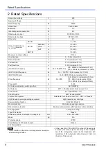
Page 8: ...nt 0 1s Post flow time s 0 30 Increment 0 1s AC TIG AC frequency Hz 50 400 STD 70 50 200Hz In increments of 1Hz 200 400Hz In increments of 10Hz MIX TIG MIX frequency Hz 0 5 10 STD 1 0 In increment of 0 1Hz MIX TIG DC ratio 10 90 STD 30 In increments of 5 Pulse frequency Hz 0 8 500 0 8 9 9Hz In increments of 0 1Hz 10 99Hz In increments of 1Hz 100 500Hz In increments of 10Hz Pulse width 5 95 AC bala...

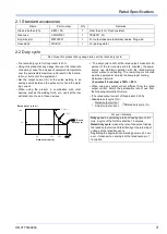
Page 9: ... 4 minutes 10 minutes x 100 40 When using any output current different from the rated output current obtain the permissible rate of use from the following calculation formula The rated output current of this product 300 A Allowable duty cycle 2 XRated duty cycle Name Part number Q ty Remarks Glass tube fuse 3A BET3 15A 1 Rear fuse Fu1 Rush resistant Gas hose CWG30101 1 TBV6X11 3m Fingertip joint M...

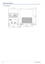
Page 10: ...Rated Specifications OMCTT5639E09 10 2 2 1 Dimensions ...

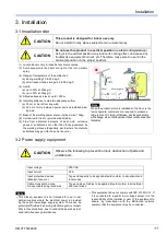
Page 11: ...to the direct sun light or the rain or water spray 3 Range of temperature of the ambient air a during welding 10 to 40 deg C b after transport and storage 20 to 55 deg C 4 Humid a up to 50 at 40deg C b up to 90 at 20deg C 5 Altitude above sea level up to 1000 m 6 Installing distance to maintain adequate airflow a 20 cm or more from any wall b 30 cm or more between power sources installed side by s...

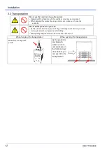
Page 12: ...he product on your own As this product is so heavy mass 51kg it is dangerous to lift it on your own Involve plural number of persons with its lifting When putting this product down do not cause a shock to it When hanging it for transportation When pushing it for transportation Make sure to hang it at 2 points As this product is provided with wheels not uni versal wheels in the front and rear of it...

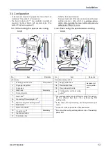
Page 13: ...water cooling torch 1 Welding power source This product 13 Supply water hose Accessory of cooling water unit 2 Argon gas regulator 14 Return water hose 3 Argon gas 15 Flow rate switch cable 4 Gas hose Accessory 16 Cooling water unit and cooling water 4 5 Grounding wire 6 Gas hose 1 1 The gas hose lead out point of the air cooling TIG welding torch is different from that of the water cooling TIG we...

Page 14: ...placement cable clamp TJM00046 Control cable assembly TWX00018 YT 20TS1 YT 208T YX 201AJ1 Replacement cable clamp TJM00038 Control cable assembly TWX00018 YT 20TSW1 YT 30TSW1 TPW1 YT 208TW TPW YT 308TW TPW YX 301A J1 Replacement cable clamp TJM00041 Control cable assembly TWX00018 Fig 1 Replacement cable clamp Fig 2 Control cable assembly TWX00018 Remove the torch cable clamp and connect it to the...

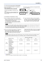
Page 15: ... center An installation error may cause damage to the torch or make it impossible to improve an insuf ficient arc start Resistor Lead wire Welding torch nozzle Ground ring ass y CWX00560 Connect either to welder case or base metal Note As the output terminal of this product employs a fingertip joint the extension cable which employs a bolt fixing termi nal cannot be connected to this product witho...

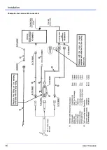
Page 16: ...Installation OMCTT5639E09 16 Example of extension cable connection ...

Page 17: ...ut of current values from the remote control unit current values appearing on the set value display may vary by about plus or minus 1A It becomes stable if you change the position of a potentiometer slightly 3 5 7 External equipment connection unit YX CB009 This connection unit enables this welding power source to change over the pages of stored welding conditions by connecting with external equip...

Page 18: ...or contents in letters in case of a trouble 1 2 3 4 5 7 8 9 6 4 Jog dial This is a dial to carry out the function of a potenti ometer setup of current and time For example to set welding current to 125A turn the dial to the right increase or to the left decrease until such a value is indicated on the set value display Note Turning the jog dial without discretion may result in the change of a set v...

Page 19: ... is turned on Make sure to set it so that the shield gas covers the welding area before the start of arc 11 Initial current Sets the current required for start ing the welding The initial current can be used only when the cra ter control is set to presence or repeat 12 Up slope Sets the time required to increase the welding current gradually to the set value after the initial current The up slope ...

Page 20: ...2 Gas supply switch Normally set it to the welding side When checking the gas flow rate set it to the inspec tion side 3 Gas outlet joint 4 Negative terminal fingertip joint 5 Terminal fingertip joint 6 Torch switch outlet 7 Outlet for remote control unit Insert the plug of a remote control unit optional item and it is securely fixed 8 Input power cables with PE The PE cable is connected to the PE...

Page 21: ...equency 10 to 500Hz Suitable for the thin plate welding fillet welding and butt welding AC TIG Standard A rectangular wave with the same peak value of output current for both electrode minus DCEN and elec trode plus DCEP periods Aluminum Magnesium Brass The general AC TIG welding can be done widely for the range of material from thin plates to thick plates Applying the pulse present mode works bet...

Page 22: ...ting filler wire during the AC period enables improvement in working property Setting the MIX TIG frequency to 1 through 2Hz makes it easier to control the insertion timing of filler wire Welding method Output waveform Image Main materials Features A C D C Weld ing method Crater Pre flow time Up slope Weld ing cur rent Down slope Spot time Crater time Post flow time Pulse current Pulse fre quency ...

Page 23: ...m the following formula as the ratio between waveform width at the electrode plus DCEP side tep in the right figure and waveform width per Hz T in the right figure AC balance tep TÅf Å 100 Waveform of AC standard TIG without pulse About AC balance adjustment The cleaning activity which is imperative for aluminum welding exerts a consider able influence upon the quality of welding including bead ap...

Page 24: ...shown as 1Hz in the rightdiagram AC standard TIG MIX TIG Note Setting example of the AC frequency with regard to a welding joint The following table shows some reference values as a guide for the aluminum A5052 welding In the actual welding operation they are not applied to all kinds of material substances AC frequency Hz 120 200 250 300 400 Welding joint Multi layer Butt Circular Fillet Butt Fill...

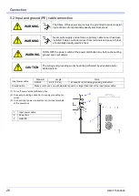
Page 25: ...e sure to provide this product and base material with class D or class C grounding work done by qualified electricians CAUTION Observe the followings to prevent a fire caused by overheat of cables Use cables at least with specified thickness Fasten all cable connections securely Name Connect to Power source side The polarity relation between the torch and base material is electrode minus DCEN 1 We...

Page 26: ... undue force on primary cable once it has been installed Cable could disconnect from terminals and pose a threat of potentially deadly electric shock WARNING TURN OFF the power switch at the power distribution box before connecting ground and input cables CAUTION The wiring and grounding work should be performed by educated and or skilled person Input power cable Diameter Length Note AWG 8 8 2 ft ...

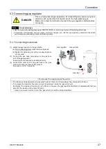
Page 27: ... instruction manual of the gas regulator carefully before connection Note About shield gas Use the high purity welding argon gas JISK1105 99 9 or more in purity as a TIG welding shield gas Incorporation of impurities such as oxygen moisture nitrogen etc into the argon gas may deteriorate the shield performance and eventually reduce the welding quality 3 1 2 Gas regulator Gas cylinder Gas inlet To ...

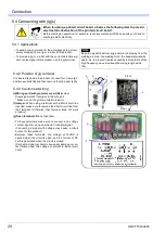
Page 28: ...n 10m 5 4 2 Position of jig terminal It is located e inside the product Loosen four crews a and two eyebolts b and then remove the top panel c Åj 5 4 3 Cautions at wiring d Wiring port with grommet cover Rear side Draw signal wires from jigs via this wire port Make a cut in the grommet wall to insert it f Jumper When using a terminal with a short circuit line inserted make sure to remove the short...

Page 29: ...R DETECTION Between these terminals the normally open relay contact contact a is connected and it is closed at all times while output current is detected Initial current welding current pulse current and base current and then crater current If there is something to be operated at the jig side while such output current is detected use these terminals for such an operation Contact rating 100VAC 0 5A...

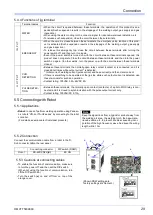
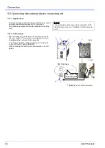
Page 30: ...g unit make sure to turn ON the DIP switch DSW2 10 When not using the function of communication turn it off again To switch the pages of stored welding conditions by connect ing external equipment sequencer to the product For details see manual of the external device connecting unit Note For preventing troubles caused by incorporation of the high frequency wave see Installation Peripheral equip me...

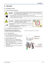
Page 31: ... and other people from arc light fly ing spatters slag and arc noises generated by welding use protective equipment Wear leather gloves and safety shoes to protect the exposed parts of your eyes and skin Prepare light shielding glasses or a welding face shield with a light shield ing filter plate appropriate to the applied welding current Prepare the ear protection device 1 Turn on the switch of t...

Page 32: ...res after every welding operation to prevent possible breakage of the flow rate switch caused by freez ing For example Take the cooling water out of the water circulating path including the flow rate switch Important To allow the inside of this product to cool down turn the power off at least 5 minutes after the com pletion of welding operations 1 Turn off POWER switch 2 Turn off the switch of the...

Page 33: ...lied current at arc start is selectable Crater End Type The weld end method at crater control Repeat can be selected Normal Terminates the welding by withdrawing a torch Torch switchb b In case torch switch is selected transition from crater current to welding current is delayed by 0 5 second when the torch switch is turned off but it is not an error Welding is terminated when the torch switch is ...

Page 34: ... appears Turn the JOG dial either clock wise or counter clockwise 4 Press the JOG dial The present set content is stored and the next set item is displayed 5 Then repeat the procedure from 2 through 4 until desired change of set contents are completed 6 Switch the FUNCTION button to WELD to start welding operation LCD display Set value JOG dial display FUNCTION button Note If you get lost during t...

Page 35: ...n the right appears 3 Press the JOG dial 4 Press the JOG dial Note The screen on the right appears on the digital ammeter 5 Turn the JOG dial to select a program number you want to delete Stored program numbers appear in series When selecting P01 6 Press the JOG dial 7 Turn the JOG dial and have YES displayed 8 Press the JOG dial To continue to delete the memories of other pro gram numbers Go to t...

Page 36: ...e JOG dial and while holding it down turn on the POWRE switch Then indication changes to 2 Turn the JOG dial until the screen on the right appears 3 Press the JOG dial 4 Turn the JOG dial and have YES displayed 5 Press the JOG dial 6 Turn the JOG dial and have YES displayed 7 Turn off the power to complete the operation Rescue Menu YC 300BP Series 1 Set Defaults No 3 Lock Memory No 3 Lock Memory N...

Page 37: ...set value can be changed even during the welding operation The set welding current can be changed even when the LCD display is showing the output voltage screen Press the JOG dial to complete the setting checking Then the indication lamp of that item is turned on and it becomes impossible to change the set value by turning the jog dial For welding condition data JOG dial FUNCTION button JOG dial O...

Page 38: ...y overwriting unless any inconvenience is caused FUNCTION button JOG dial Operation Set value display LCD display 1 Set FUNCTION button to PLAY Note The screen on the right appears on the digital amme ter 2 Turn the JOG dial and select a program number to be reproduced The stored program numbers are indicated in ascending order If there is no program stored the display is still indicating P when t...

Page 39: ... other than 0 They assume that the output current is set to pulse present In the case of pulse absent there should be no pulse current or pulse width 6 4 1 No Crater 6 4 2 Crater DANGER Pressing the torch switch by mistake may cause an electric shock When inspecting or replacing any torch parts make sure to turn the power switch off in advance Torch switch Output current Shield gas ON OFF Pulse cu...

Page 40: ... the torch switch is turned off during the arc spot time the welding operation is terminated immediately Torch switch Output current Shield gas ON OFF ON ON OFF 1 2 3 A Pulse current Welding current Initial current Pre flow Up slope Down slope Up slope Crater current Repeating section A 1 When the torch switch is turned OFF self hold starts the Up slope starts 2 When the torch switch is turned ON ...

Page 41: ...r is attached correctly Breakage or loose attachment Gas inlet joint Breakage or loose attachment Cooling fan If it makes any unusual rotation noise If it generates cooling wind all right Top Bottom Sides Handle Breakage or loose attachment If there is any defect additional fastening parts replacement etc are required Casters Cases Loose attachment Overall Is there any trace of heat generation suc...

Page 42: ...ure to observe the followings To secure physical safety make sure that a qualified person or a person who is familiar with the welding machine takes care of a regular check Make sure to turn off the power and other switches of all devices for safety reasons before starting a regular check unless there is the absolute necessity of keeping them turned on Means this product distribution box and any o...

Page 43: ... etc and hoses for gases and for water supply and drainage when using the water cooling torch check those items that are not covered by the daily check See page 12 1 intensively Inspection and mainte nance of consumable parts A cooling fan and electrolytic capacitor have a given electrical and mechanical life respectively When they are used under the rated specifications the life of the cooling fa...

Page 44: ...the unit input cable from the power box switch secondary side and the unit input terminal make sure to switch OFF the power box Primary side 3 Short circuit the unit input terminals collectively total 3 terminals 4 Keep the power switch ON side 5 Short circuit the diode D1 wire 8 and wire 9 6 Short circuit the capacitors C1 and The capacitors may still have voltage Wait for 5 min utes or more afte...

Page 45: ...connectors on the PC board as they were Return the dust cover top panel right panel and left panel as they were Connect the input power cable to the input terminal and return the terminal cover Connect the input power cable to the power box switch WARNING If power is ON without removing the jumper bar for test devices may be damaged or burnt out CAUTION Unless cables removed for test are returned ...

Page 46: ... on with the top panel and or side panel of this product removed The electromagnetic force may cause troubles deformation mechanical contact etc to the inside devices and parts and may break them and or affect their functions and performance Those error code is also indi cated on the 7 segment LED on the PC Board ZUEP1398 inside the product E r r Code Message Remedy E r r 01 EmergencyStop An emerg...

Page 47: ... this product Please contact sales distributor or Panasonic representative E r r 13 Sec OverVoltage During the MIX TIG and AC TIG welding the output side cables are used winding them in small coils Use the output side cables preferably without winding them in coils When using them in a state of coils unavoidably wind them in 300É or larger coils See section Connection Output cables To reset turn t...

Page 48: ...s not ON O O O GAS switch is placed to Purge O Gas cylinder and Gas regulator Main cock is not open Gas nearly runs short Insufficient flow rate O O O O O Excessive flow rate O O Gas hose From gas cylin der to torch Loose connections Hose is damaged O O Torch cable Torch is bent at acute angle Coating is damaged Sign of insulation deterioration O O O Torch switch is not ON O Around the torch body ...

Page 49: ...Parts list OMCTT5639E09 49 9 Parts list ...

Page 50: ...r 2 40W 75Ω SFW40A750 21 R11 12 SMRK220W101K Resistor 2 SMRK220W10 22 R5 6 19 20 SMRK220W200K Resistor 4 SMRK220W20 24 R21 22 27 28 CEX00083 Resistor 2 CEX00083 25 CTl YCA6 C T 1 TN300A4VB15 26 C1 2 YCA23 Capacitor ass y 2 RWE45LGSN1 27 C4 5 CEX00111 Capacitor ass y 2 CEX00111 28 C33 36 CEX00109 Capacitor ass y 1 CEX00109 29 C28 30 CEX00094 Capacitor ass y 1 CEX00094 30 C6 10 12 26 27 DEX00114 Cap...

Page 51: ...8 50 ZUEP1395 PC Board 1 Operation ZUEP1395 51 ZUEP0806 PC Board 1 Filter ZUEP0806 52 ZUEP0998 PC Board 2 Filter ZUEP0998 53 ZUEP1363 PC Board 2 ZUEP1363 54 ZUEP1220 PC Board 2 Driver ZUEP1220 55 ZUEP1399 PC Board 1 Super impose ZUEP1399 56 ZUEP1364 PC Board 1 ZUEP1364 57 ZUEP1253A1 PC Board 3 ZUEP1253A1 58 YMW4 Handle 2 AP829 2 59 Cord lock 1 68 YZA EEP001 Cooling fan 1 PUDC24D4 69 ZUEP1433 PC Bo...

Page 52: ...OMCTT5639E09 52 ...

Page 53: ...Circuit diagram OMCTT5639E09 53 10 Circuit diagram NF9 NF8 ...

Page 54: ...Circuit diagram OMCTT5639E09 54 10 1 Enlarged left half NF8 MCB ...

Page 55: ...Circuit diagram OMCTT5639E09 55 10 2 Enlarged right half NF9 ...

Page 56: ...50 40 50 15 30 1 0 1 6 5 Fillet 45 60 45 55 45 60 20 40 1 0 1 6 5 T shape 50 60 50 60 50 60 10 35 1 0 1 6 5 1 5 Butt 60 100 60 80 60 70 15 80 1 6 5 Lap 60 100 70 100 80 90 15 80 1 6 5 Fillet 60 80 60 70 60 70 20 40 1 6 5 T shape 70 80 70 90 70 90 10 20 1 6 5 2 5 Butt 100 120 90 110 90 110 20 80 1 5 2 5 5 Lap 110 130 100 120 100 120 20 80 1 5 2 5 5 Fillet 100 120 90 110 90 110 28 30 1 5 2 5 5 T sha...

Page 57: ...tt 125 145 115 135 120 140 30 2 5 3 0 8 Lap 140 160 120 145 130 160 25 2 5 8 Fillet 125 145 115 135 130 150 30 2 5 8 T shape 140 160 115 135 140 160 25 1 5 2 5 8 4 5 Butt 190 220 190 220 180 210 28 3 0 10 Lap 210 240 190 220 180 210 28 3 0 10 Fillet 190 220 180 210 180 210 28 3 0 10 T shape 210 240 190 220 180 210 15 3 0 10 6 0 Butt 260 300 220 360 210 225 25 3 5 4 5 12 Lap 290 340 220 360 210 225...

Page 58: ... the cleaning activities also become less efficient and the weld ing quality in bead appearance penetration etc is considerably affected 11 1 4 Filler wire For the filler wire material which is same as base material is used in general In special cases including the welding of different metal etc select material depending on your purposes As for the diameter of filler wire an appropriate thickness ...

Page 59: ...lding method Crater Pulse AC waveform DC TIG OFF OFF Standard AC TIG ON ON Hard MIX TIG Repeat Soft Spot Column with thick frame for Pulse ON NA Method Crater Pre flow time Initial cur rent Up slope Weld ing cur rent Down slope Spot time Crater time Post flow time Pulse current Pulse fre quency Pulse width AC bal ance AC frequency MIX fre quency DC ratio DC TIG OFF ON Repeat Spot AC TIG OFF ON Rep...

Page 60: ...er Material to be welded Remarks Prepared on Prepared by P01 P02 P03 P04 P05 P06 P07 P08 P09 P10 P11 P12 P13 P14 P15 P16 P17 P18 P19 P20 P21 P22 P23 P24 P25 P26 P27 P28 P29 P30 P31 P32 P33 P34 P35 P36 P37 P38 P39 P40 P41 P42 P43 P44 P45 P46 P47 P48 P49 P50 ...

Page 61: ...nly in designated national waste electronic collection schemes and not in the ordinary dust bin For business users in the European Union If you wish to discard electrical and electronic equipment please contact your dealer or supplier for further information Information on Disposal in other Countries outside the European Union This symbol is only valid in the European Union If you wish to discard ...

Page 62: ...OMCTT5639E09 62 ...

Page 63: ...OMCTT5639E09 63 ...

Page 64: ...09 パナソニック スマートファクトリーソリューションズ株式会社 571 8502 大阪府門真市松葉町 2 番 7 号 Panasonic Smart Factory Solutions Co Ltd 2 7 Matsuba cho Kadoma City Osaka 571 8502 Japan Panasonic Smart Factory Solutions Co Ltd Printed in Japan 2007 ...

Reviews: