Installation
OMCTT5639E09
11
3. Installation
3.1 Installation siter
3.2 Power supply equipment
Note
• This Class A equipment is not intended for use in resi
-
dential locations where the electrical power is provided
by the public low-voltage supply system. There can be
potential difficulties in ensuring electromagnetic compati
-
bility in those locations, due to conducted as well as radi
-
ated radio-frequency disturbances.
• This equipment does not comply with IEC 61000-3-12. If
it is connected to a public low voltage system, it is the
responsibility of the installer or user of the equipment to
ensure, by consultation with the distribution network
operator, that the equipment may be connected.
CAUTION
This product is designed for indoor use only.
Do not install it in any places subject to rain or water spray.
CAUTION
Do not use this product in a vertical position
(i.e.: with its control panel side up).
Using it in the vertical position may reduce its cooling effect, and cause any
troubles like equipment burnout, etc. Therefore, make sure to use it in the
horizontal position (in the proper position).
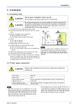
(1) Locate indoors only in industrial environment area.
(2) Avoid exposure to the direct sun light or the rain or water
spray.
(3) Range of temperature of the ambient air:
(a) during welding:10 to 40 deg-C,
(b) after transport and storage:-20 to 55 deg-C
(4) Humid:
(a) up to 50% at 40deg-C,
(b) up to 90% at 20deg-C
(5) Altitude above sea level: up to 1000 m.
(6) Installing distance to maintain adequate airflow:
(a) 20 cm or more from any wall,
(b) 30 cm or more between power sources installed side-
by-side.
(7) Base of the welding power source inclined:max. 10deg.
(8) Avoid wind to the arc (provide windshields.)
(9) Free from abnormal amounts of dust, acid, corrosive
gases or substances etc. other than those generated by
the welding process (Especially, avoid where the metallic
substance may get into the power source.)
Note
When the product, which is installed on the floor, is too
low to operate, customers are required to prepare a
table to mount it. (And, in that case, provide such a table
with a flange, etc. so that the product does not slip down from
the table.)
20cm
30cm or more
CAUTION
Observe the following to prevent burnout, destruction of parts and
unstable arc.
Input voltage
200 VAC
Input current
32 A
Input protective devices
(Breaker, fuse etc.)
Type and capacity to be applied should conform to all national and
local codes.
Cable cross section area
for input cable and ground wire
Type and size of cables to be applied should conform to all national
and local codes.
Summary of Contents for YC-300BP2YAF
Page 10: ...Rated Specifications OMCTT5639E09 10 2 2 1 Dimensions ...
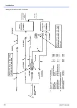
Page 16: ...Installation OMCTT5639E09 16 Example of extension cable connection ...
Page 49: ...Parts list OMCTT5639E09 49 9 Parts list ...
Page 52: ...OMCTT5639E09 52 ...
Page 53: ...Circuit diagram OMCTT5639E09 53 10 Circuit diagram NF9 NF8 ...
Page 54: ...Circuit diagram OMCTT5639E09 54 10 1 Enlarged left half NF8 MCB ...
Page 55: ...Circuit diagram OMCTT5639E09 55 10 2 Enlarged right half NF9 ...
Page 62: ...OMCTT5639E09 62 ...
Page 63: ...OMCTT5639E09 63 ...

