background image

Chapter 5

Operations — Updating the firmware

ENGLISH - 233

Updating the firmware

1)  Extract the compressed file downloaded from the website.


f

The firmware update tool (executable file in exe format) is generated.

File name (example): FirmUpdateTool_MZ20K_101.exe

(Update tool for the PT-MZ20K/PT-MZ17K/PT-MZ14K/PT-MZ11K with version 1.01)

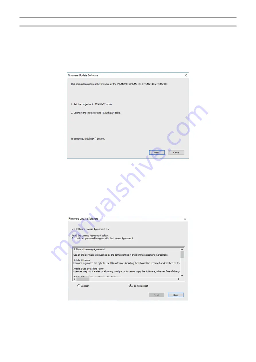
2)  Double-click the executable file generated by extracting.


f

The update tool is started up, and the confirmation screen is displayed.

3)  Confirm the status of the projector.


f

Confirm that the projector to be updated is in the standby mode.

4)  Confirm the connection status.


f

Confirm that the projector to be updated and the computer to be used for update are correctly connected to 

LAN.

5)  Click [Next].


f

The license agreement screen is displayed.


f

Confirm the content of the license agreement.


f

The update tool will end by clicking [Close].

Summary of Contents for PT-MZ20K

Page 1: ...or 100 V 120 V LBX Black model z z for other countries or regions with power cord for 200 V 240 V LBEJ LBE Black model LWEJ LWE White model Before operating this product please read the instructions c...

Page 2: ...nnecting example AV equipment 48 Connecting example Computers 49 Connecting example using DIGITAL LINK 50 Connecting example when using the contrast synchronization function shutter synchronization fu...

Page 3: ...TTING 121 FREEZE 123 WAVEFORM MONITOR 123 CUT OFF 124 PROJECTOR SETUP menu 125 PROJECTOR ID 125 PROJECTION METHOD 125 LENS 126 OPERATION SETTING 130 LIGHT OUTPUT 133 STANDBY MODE 133 QUICK STARTUP 134...

Page 4: ...e data to another projector via LAN 225 Copying the data to another projector using USB 227 Using HDMI CEC function 229 Connecting a CEC compatible device 229 Setting the projector and CEC compatible...

Page 5: ...earthing type mains socket This is a safety feature If you are unable to insert the plug into the mains socket contact an electrician Do not defeat the purpose of the earthing plug WARNING This equip...

Page 6: ...to the presence of important operating and maintenance servicing instructions in the literature accompanying the product WARNING Do not look at the light emitted from the lens while the projector is b...

Page 7: ...rd If you use the accessory cord in such situations fire may result CAUTION North Middle South America Taiwan This equipment is equipped with a three pin grounding type power plug Do not remove the gr...

Page 8: ...erated in a commercial environment This equipment generates uses and can radiate radio frequency energy and if not installed and used in accordance with the instruction manual may cause harmful interf...

Page 9: ...danger of severe electrical shock if the cut off plug is inserted into any 13 amp socket If a new plug is to be fitted please observe the wiring code as shown below If in any doubt please consult a qu...

Page 10: ...nside the hazard zone even for a moment In the case of risk group 2 safe use without damaging the eyes is possible in all circumstances except deliberately staring into the light projected from the pr...

Page 11: ...T850 ET EMT800 1 6 0 11 0 11 0 13 0 13 1 HD Hazard Distance 2 The values of D1 to D4 will change in accordance with the lens shift amount Each value in the table is the maximum value Note f f The valu...

Page 12: ...t supporting 15 A independently Using an outlet together with another device may result in fires due to heat generation Do not overload the wall outlet If the power supply is overloaded ex by using to...

Page 13: ...r on the ceiling should only be carried out by a qualified technician If installation is not carried out and secured correctly it can cause injury or accidents such as electric shocks r r ACCESSORIES...

Page 14: ...t place the projector in extremely hot locations Doing so will cause the outer casing or internal components to deteriorate or result in fire f f Take particular care in locations exposed to direct su...

Page 15: ...Do not attach the air filter unit while it is wet Doing so may result in electric shock or malfunctions f f After you clean the air filter units dry them thoroughly before reattaching them Ask your de...

Page 16: ...do pela bateria pode irritar a garganta danificar o lacre do inv lucro ou o vazamento provocar calor ruptura da blindagem e produzir fogo devido ao curto circuito dos terminais N o incinere nem aque a...

Page 17: ...eloped independently by or for Panasonic Connect Co Ltd 2 the software owned by third party and licensed to Panasonic Connect Co Ltd 3 the software licensed under the GNU General Public License Versio...

Page 18: ...rce More advanced rendition in wide range of usages is now possible With the superior compatibility with the devices other than projectors more advanced rendition in wide range of usage is possible Lo...

Page 19: ...ENGLISH 19 Chapter 1 Preparation This chapter describes things you need to know or check before using the projector...

Page 20: ...g the projector The person responsible shall be trained by Panasonic Connect Co Ltd before starting to use the projector Note f f Information such as training FDA variance application installation che...

Page 21: ...mperature around the projector or the increased internal temperature caused by the light from its light source and it will be unstable especially right after the projection has started This projector...

Page 22: ...the projector use commercially available ISO 898 1 standard screws made of carbon steel or alloy steel Screw diameter M6 tapping depth inside the projector 12 mm 15 32 torque 4 0 5 N m Positions of s...

Page 23: ...n such as your ID password credit card number g g Content of an Email f f Illegally accessed A malicious third party may access your personal or corporate network without authorization and engage in t...

Page 24: ...YFB100G ET YFB200G and peripheral devices by other manufacturers twisted pair cable transmitters such as the XTP transmitter of Extron Electronics that use the same HDBaseTTM standard For the devices...

Page 25: ...s according to the shape of the screen through use of a camera f f Projector Network Setup Software This application software allows to set the network information such as the IP addresses and the pro...

Page 26: ...the following characteristics f f Depending on the operating environment temperature the luminance of the light source will decrease The higher the temperature becomes the more the luminance of the l...

Page 27: ...iscard the power cord cap and packaging material properly f f Do not use the supplied power cord for devices other than this projector f f For lost accessories consult your dealer f f Store small part...

Page 28: ...ils contact your dealer 3 The suffix of the Model No differs depending on the country Example of the Model No with suffix for AJ WM50 Series AJ WM50E AJ WM50G1 AJ WM50G2 AJ WM50GAN AJ WM50GPX AJ WM50P...

Page 29: ...to project x page 67 8 FUNCTION button Assigns a frequently used operation as a shortcut button x page 75 When the FUNCTION button is held down the FUNCTION BUTTON screen is displayed x page 145 9 Num...

Page 30: ...projector operate the remote control within a distance approximately 30 m 98 5 from the remote control signal receiver The remote control can control at angles of up to 30 vertically and horizontally...

Page 31: ...of the air filter unit 6 Adjustable feet Adjusts the projection angle 7 Intake vent 8 Exhaust vent 9 Connecting terminals x page 33 10 MAIN POWER switch Turns on off the main power 11 Power cord holde...

Page 32: ...ent of the projector For details of the Smart Projector Control visit the following website https panasonic net cns projector r r Control panel 7 9 6 5 8 2 10 1 3 4 1 POWER ON button Sets the projecto...

Page 33: ...nput to the SERIAL MULTI SYNC IN terminal This terminal is also used to connect multiple projectors when balancing the contrast as a combined screen or synchronizing the effects using the shutter func...

Page 34: ...o ALL so you can use it as it is Set the ID numbers of the projector body and remote control as necessary For details on setting the ID number of the remote control refer to Setting ID number of the r...

Page 35: ...ENGLISH 35 Chapter 2 Getting Started This chapter describes things you need to do before using the projector such as the setup and connections...

Page 36: ...the outlet f f Use the power cord matching the used power supply voltage and outlet shape Note f f The supplied power cords vary depending on the country or region where you purchased the product Inst...

Page 37: ...accordance with the image to project FLOOR CEILING Set in accordance with the image to project Note f f In the portrait setting the on screen menu is displayed sideways To display the on screen menu...

Page 38: ...or Attention f f To ensure projector performance and security installation of the Ceiling Mount Bracket must be carried out by your dealer or a qualified technician Projected image and throw distance...

Page 39: ...te f f For the adjustment range of the projected image position with the lens shift refer to Lens shift range x page 72 GEOMETRY projection range VERTICAL KEYSTONE viewed from the side HORIZONTAL KEYS...

Page 40: ...ET EMW400 22 15 8 8 1 5 3 7 0 9 2 2 ET EMW500 22 15 8 8 1 2 3 0 7 1 7 ET EMT750 ET EMT700 45 40 20 15 0 6 1 1 0 3 0 6 ET EMT850 ET EMT800 45 40 20 15 0 3 0 6 0 2 0 3 1 When VERTICAL KEYSTONE and HORI...

Page 41: ...7 10 50 10 34 14 89 15 24 600 8 077 12 923 17 57 27 59 6 34 7 40 7 23 9 15 9 10 12 61 12 42 17 87 1 The throw ratio is based on the value during projection with the projected image size of 2 54 m 100...

Page 42: ...37 1 The throw ratio is based on the value during projection with the projected image size of 2 54 m 100 Unit m Lens type Zoom Lens Height position H Projection lens Model No ET EMT750 ET EMT700 ET E...

Page 43: ...4 1 The throw ratio is based on the value during projection with the projected image size of 2 54 m 100 Unit m Lens type Zoom Lens Height position H Projection lens Model No ET EMT750 ET EMT700 ET EMT...

Page 44: ...660 0 830 1 4 3 0 5402 x SD 0 0397 0 6828 x SD 0 0397 ET EMW400 0 690 0 950 1 16 10 0 6003 x SD 0 0518 0 8303 x SD 0 0460 0 690 0 950 1 16 9 0 6170 x SD 0 0518 0 8534 x SD 0 0460 0 830 1 15 1 4 3 0 6...

Page 45: ...of the product resulting from the use of projection lenses which are not manufactured by Panasonic Connect Co Ltd Be sure to use the specified projection lenses Note f f For the adjustment procedure...

Page 46: ...lens fixing screw f f When attaching a projection lens other than the Zoom Lens Model No ET EMU100 to the projector secure the projection lens to the screw hole on the right of the projection lens usi...

Page 47: ...move the top slide cover Fig 3 f f Slide the top slide cover until the top slide cover attachment line is visible Once the top slide cover attachment line is visible remove it by lifting 3 While holdi...

Page 48: ...ing example when using the contrast synchronization function shutter synchronization function x page 51 f f Some computer models or graphic cards are not compatible with the projector f f Connect usin...

Page 49: ...e HDMI cable use an HDMI High Speed cable that conforms to the HDMI standards However when the following 4K image signal exceeding the supported transmission speed of the HDMI High Speed cable is to b...

Page 50: ...or is used include it in the measurement f f Do not use a switching hub between the twisted pair cable transmitter and the projector f f When connecting to the projector using a twisted pair cable tra...

Page 51: ...e respective manufacturers Connecting example when using the contrast synchronization function shutter synchronization function In a case to construct a multi display by linking projected images from...

Page 52: ...OR SYNC x page 141 f f The menu items in the PROJECTOR SETUP menu MULTI PROJECTOR SYNC are the same as the following setting items g g The PICTURE menu DYNAMIC CONTRAST NX USER MULTI PROJECTOR SYNC g...

Page 53: ...ENGLISH 53 Chapter 3 Basic Operations This chapter describes basic operations to start with...

Page 54: ...36 Note f f The supplied power cords vary depending on the country or region where you purchased the product How to attach the power cord 1 Confirm that the power cord holder is raised so that the pow...

Page 55: ...when the light source indicator LIGHT or the temperature indicator TEMP is blinking x page 239 Blinking The power is switched off standby mode Projection will start when the POWER ON button is pressed...

Page 56: ...jector 2 Connect the power plug to an outlet 3 Press the ON side of the MAIN POWER switch to turn on the power f f The power indicator ON G STANDBY R lights blinks red and the projector enters the sta...

Page 57: ...can change the settings by menu operations If you press the MENU button while the INITIAL SETTING screen is displayed you can go back to the previous screen Focus adjustment Adjust the focus to displa...

Page 58: ...displayed Note f f For the relationship between the brightness and the runtime refer to Relationship between brightness and runtime x page 59 f f For details on each setting item refer to the PROJECTO...

Page 59: ...0 12 000 23 000 40 0 8 000 25 000 1 Estimated runtime is the time until the brightness decreases to approximately half of the time of delivery when the projector is used with the PICTURE menu DYNAMIC...

Page 60: ...00 0 11 000 20 000 80 0 8 800 21 500 60 0 6 600 23 000 40 0 4 400 25 000 1 Estimated runtime is the time until the brightness decreases to approximately half of the time of delivery when the projector...

Page 61: ...D INITIAL SETTING FRONT REAR FLOOR CEILING MENU SELECT FRONT AUTO 2 Press the ENTER button to proceed to the initial setting Initial setting standby mode Set the operation mode during standby The fact...

Page 62: ...tting f f The setting will change each time you press the button 16 10 5 7 SCREEN POSITION Set as necessary for the screen in use INITIAL SETTING SET CHANGE MENU SELECT SCREEN FORMAT ENTER 2 Press as...

Page 63: ...tting you can change the setting from the PROJECTOR SETUP menu DATE AND TIME To set the date and time automatically refer to Setting the date and time automatically x page 139 1 Press as to select an...

Page 64: ...d 5 Press asqw to select the text and press the ENTER button to enter the text f f Up to 16 characters can be entered f f The password cannot be blank 6 After the password is entered press asqw to sel...

Page 65: ...for the operation of the menu screen 3 Execute the lens calibration f f Execute the lens calibration when using the projector for the first time after attaching the projection lens x page 70 4 Select...

Page 66: ...f For approximately five seconds after the projector is turned off the indicator does not light up even if the power is turned on f f Even when the STANDBY button is pressed and the projector is switc...

Page 67: ...LINK Switches the input to DIGITAL LINK The image of the signal input to the DIGITAL LINK terminal is projected SDI Switches the input to SDI The image of the signal input to the SDI IN terminal is p...

Page 68: ...nput name selected in the DIGITAL LINK output supported device are displayed in the display section of the DIGITAL LINK in the input selection screen Adjusting the focus zoom and lens shift Adjust the...

Page 69: ...he projector is switched off during the lens shift adjustment lens calibration needs to be performed the next time the projector is switched on x page 130 f f When the main power is switched off durin...

Page 70: ...rted f f After completing the calibration the projection lens will move to the home position Note f f PROGRESS is displayed in the menu during lens calibration The operation cannot be canceled during...

Page 71: ...e projection lens is not moved to the correct home position when the PROJECTOR SETUP menu LENS LENS CALIBRATION is not executed f f The home position does not match with the optical image center posit...

Page 72: ...llowing illustration indicates the lens shift range when the projector is installed on desk floor Projection lens Model No ET EMW400 ET EMW500 ET EMS650 ET EMS600 ET EMT750 ET EMT700 ET EMT850 ET EMT8...

Page 73: ...memory formatted in FAT16 or FAT32 f f Only the single partition structure is supported Attaching the USB memory 1 Insert the USB memory all the way in to the USB terminal Attention f f Take care of t...

Page 74: ...R will blink slowly in green while the shutter function is in use shutter closed f f The fade in fade out time of the image can be set by the DISPLAY OPTION menu SHUTTER SETTING Using the on screen di...

Page 75: ...heck the condition of the projector ten internal test patterns and up to three user registered test patterns can be displayed button 1 Press the TEST PATTERN button f f The test pattern and the main m...

Page 76: ...together you can operate all the projectors simultaneously or each projector individually using a single remote control if a unique ID number is assigned to each projector After setting the ID number...

Page 77: ...ed if the remote control is left with dead batteries Set the same ID number again when the batteries are replaced Note f f When the ID number of the remote control is set to 0 you can control the proj...

Page 78: ...78 ENGLISH Chapter 4 Settings This chapter describes the settings and adjustments you can make using the on screen menu...

Page 79: ...NCED MENU DISPLAY LANGUAGE DISPLAY OPTION PROJECTOR SETUP TEST PATTERN SIGNAL LIST SECURITY NETWORK MENU SELECT SUB MENU ENTER 2 Press as to select an item from the main menu f f The selected item is...

Page 80: ...low cursor by the factory default f f In the portrait setting the on screen menu is displayed sideways To display the on screen menu vertically change the setting of the DISPLAY OPTION menu ON SCREEN...

Page 81: ...MPLE PICTURE Sub menu item Factory default SIMPLE mode Page PICTURE MODE STANDARD 1 l 84 CONTRAST 0 l 85 BRIGHTNESS 0 l 85 COLOR 7 2 l 86 TINT 0 86 COLOR TEMPERATURE DEFAULT 2 86 GAMMA 0 87 SYSTEM DAY...

Page 82: ...GE ROTATION OFF 119 BACK COLOR BLUE 119 STARTUP LOGO DEFAULT LOGO l 119 UNIFORMITY OFF 120 SHUTTER SETTING 121 FREEZE 123 WAVEFORM MONITOR OFF 123 CUT OFF 124 PROJECTOR SETUP Sub menu item Factory def...

Page 83: ...not be set if the optional Wireless Module Model No AJ WM50 Series is not attached to the USB terminal Note f f Some items may not be adjusted or used for certain signal formats to be input to the pro...

Page 84: ...tandard for medical imaging devices Although the DICOM name is used the projector is not a medical device and display images should not be used for medical purposes such as diagnosis f f If the ENTER...

Page 85: ...onfirmation screen is displayed 6 Press qw to select OK and press the ENTER button f f The settings in the PICTURE menu except for SYSTEM SELECTOR and DEFAULT PICTURE MODE are overwritten with the def...

Page 86: ...color temperature if the white areas of the projected image are bluish or reddish Adjusting with color temperature 1 Press as to select COLOR TEMPERATURE 2 Press qw or the ENTER button f f The COLOR...

Page 87: ...ss adequate adjustment is made If the adjustment does not look suitable you can press the DEFAULT button on the remote control to return the setting for the selected item only to the factory default s...

Page 88: ...s become sharper 0 15 Press q Contours become softer Note f f If you press w while the adjustment value is 15 the value will become 0 If you press q while the adjustment value is 0 the value will beco...

Page 89: ...TRAST NX individual adjustment screen is displayed 3 Press qw to select USER 4 Press the ENTER button f f The DYNAMIC CONTRAST NX screen is displayed 5 Press as to select the item to set f f The items...

Page 90: ...s set to anything other than DISABLE the following are the conditions to turn the light source back on again from the state that the light source has turned off by this function g g When the brightnes...

Page 91: ...ory setting 46 LIGHTS OUT TIMER Time setting until the light turns off DISABLE Does not turn off the light source 0 0s 10 0s Turns off the light source when the brightness level of the image signal be...

Page 92: ...ors SYSTEM SELECTOR The projector will automatically detect the input signal but you can set the system method manually when an unstable signal is input Set the system method matching the input signal...

Page 93: ...menu PICTURE MODE is switched to the picture mode set in DEFAULT PICTURE MODE g g When a new signal is input g g When the deleted signal is input again after the registered signal has been deleted g g...

Page 94: ...ment Vertical up and down adjustment Press a The image position moves up Press s The image position moves down Horizontal right and left adjustment Press w The image position moves to the right Press...

Page 95: ...he aspect ratio for the input signals is selected the images will appear differently from the originals Be careful of this when selecting the aspect ratio f f If using the projector in places such as...

Page 96: ...oes not perform geometric adjustment KEYSTONE Adjusts any trapezoidal distortion in the projected image CORNER CORRECTION Adjusts any distortion in the four corners of the projected image CURVED CORRE...

Page 97: ...es to be corrected For details of operation refer to Adjusting distortion with FREE GRID x page 98 CURVED CORRECTION LENS THROW RATIO Set the throw ratio Select the value close to the actual projectio...

Page 98: ...ation refer to Adjusting distortion with FREE GRID x page 98 Adjusting to desired linearity 1 Press as to select GEOMETRY 2 Press qw to select CORNER CORRECTION 3 Press the ENTER button f f The GEOMET...

Page 99: ...ress as to select CONTROL POINTS 10 Press qw to switch the item f f The items will switch each time you press the button POINT Select this item when adjusting by selecting one intersection from the in...

Page 100: ...TONE CORNER CORRECTION CURVED CORRECTION PC 1 PC 2 and PC 3 f f Even if GRID RESOLUTION or CONTROL POINTS is reselected the correction data adjusted before the reselection is maintained f f By selecti...

Page 101: ...e all the correction data select each item and execute INITIALIZE individually f f When the projector is initialized by one of the following methods all data in FREE GRID are initialized g g When init...

Page 102: ...IGITAL CINEMA REALITY the picture quality will degrade when a signal other than the 2 2 pulldown is set as 25p FIXED or 30p FIXED Vertical resolution will degrade BLANKING Adjust the blanking width if...

Page 103: ...mizer function refer to the PROJECTOR SETUP menu LENS ACTIVE FOCUS OPTIMIZER x page 129 For details of the test pattern refer to TEST PATTERN menu x page 155 It is recommended that edge blending is ad...

Page 104: ...PPED BLACK LEVEL 15 Press the ENTER button f f The adjustment area in the projected image becomes temporarily bright and the NON OVERLAPPED BLACK LEVEL screen is displayed f f RED GREEN and BLUE can b...

Page 105: ...t the position of the adjustment point f f Press as to adjust VERTICAL when UPPER FREE SHAPE or LOWER FREE SHAPE is selected in Step 19 f f Press qw to adjust HORIZONTAL when LEFT FREE SHAPE or RIGHT...

Page 106: ...erform edge blending together with the adjustment of GEOMETRY x page 96 If NON OVERLAPPED BLACK LEVEL is deformed by correcting the distortion of the projected image with GEOMETRY perform the adjustme...

Page 107: ...PROJECTOR SETUP menu INITIALIZE USER SETTINGS OTHER USER SETTING to INITIALIZE FRAME RESPONSE Set image frame delay 1 Press as to select FRAME RESPONSE 2 Press qw to switch the item f f The items will...

Page 108: ...AY LANGUAGE SELECT SET f f Various menus settings adjustment screens control button names etc are displayed in the selected language f f The language can be changed to English German French Spanish It...

Page 109: ...ON the test pattern for the selected color is displayed 7 Press as to select RED GREEN or BLUE f f Only GAIN can be adjusted when WHITE is selected for 3COLORS 8 Press qw to adjust f f The adjustment...

Page 110: ...qw to switch the item f f The items will switch each time you press the button OFF Standard setting USER For each signal format of RGB signal and YCBCR YPBPR signal six colors of red green blue cyan m...

Page 111: ...n is ready for use the state of readiness to use the backup function is canceled To switch to the backup input signal using the backup function again switch to the primary input or secondary input f f...

Page 112: ...t from the HDMI terminal of a computer or other device is input to the HDMI IN 1 terminal or the HDMI IN 2 terminal Note f f The optimal setting varies depending on the output setting of the connected...

Page 113: ...will switch each time you press the button DEFAULT Standard setting SCREEN FIT Changes the EDID data according to the SCREEN FORMAT setting USER Set the RESOLUTION and VERTICAL SCAN FREQUENCY items as...

Page 114: ...omatically selects LEVEL A or LEVEL B LEVEL A Fixes the mapping method to 3G SDI Level A LEVEL B Fixes the mapping method to 3G SDI Level B Note f f This function does not operate when the HD SDI sign...

Page 115: ...witch each time you press the button AUTO Automatically sets the signal level 64 940 Select this item when the signal output from the HDMI terminal of an external device such as a Blu ray disc player...

Page 116: ...f f Proceed to Step 10 when DEFAULT or SCREEN FIT is selected 6 Press the ENTER button f f The RESOLUTION screen is displayed 7 Press asqw to select RESOLUTION f f Select 1024x768p 1280x720p 1280x800p...

Page 117: ...f the menu screen OSD 1 Press as to select ON SCREEN DISPLAY 2 Press the ENTER button f f The ON SCREEN DISPLAY screen is displayed 3 Press as to select OSD ROTATION 4 Press qw to switch the item f f...

Page 118: ...g WARNING MESSAGE Set the display hide of the warning message 1 Press as to select ON SCREEN DISPLAY 2 Press the ENTER button f f The ON SCREEN DISPLAY screen is displayed 3 Press as to select WARNING...

Page 119: ...LOGO image use Logo Transfer Software The software can be downloaded from the following website https panasonic net cns projector When transferring logos via the optional DIGITAL LINK output supporte...

Page 120: ...NTER button f f The UNIFORMITY USER CORRECTION screen is displayed 3 Press as to select ADJUSTMENT LEVEL 4 Press qw to switch the item f f The items will switch each time you press the button 1 5 Sele...

Page 121: ...lly f f To initialize correction data in UNIFORMITY at once select the PROJECTOR SETUP menu INITIALIZE UNIFORMITY ONLY and execute the initialization f f TEST PATTERN is not initialized Select the ite...

Page 122: ...s used Set this item only on one projector that becomes the synchronization source of the shutter operation within the linked projectors SUB Select this item when the contrast synchronization function...

Page 123: ...ation will follow the setting of the DISPLAY OPTION menu SHUTTER SETTING set in that projector FREEZE Use the freeze function to pause the projected image temporarily regardless of the playback of the...

Page 124: ...ignal to the 0 position of the waveform monitor 4 Adjust bright red areas f f Use RED in WHITE BALANCE HIGH to adjust the white level 100 of the image signal to the 100 position of the waveform monito...

Page 125: ...with other ID numbers f f Refer to Setting ID number of the remote control x page 76 for how to set the ID number on the remote control PROJECTION METHOD Set the projection method in accordance with...

Page 126: ...position horizontal position focus position zoom position and periphery focus position can be saved and loaded When the projector is used for the first time or when the projection lens is replaced exe...

Page 127: ...SITION FOCUS POSITION ZOOM POSITION PERIPHERY FOCUS POSITION are displayed in the LENS MEMORY LOAD screen 7 Press as to select the item to load and press the ENTER button f f The confirmation screen i...

Page 128: ...DIT screen is displayed 7 Press as to select LENS MEMORY NAME CHANGE 8 Press the ENTER button f f The LENS MEMORY NAME CHANGE screen is displayed f f The name of the saved lens memory and its lens pos...

Page 129: ...e LENS screen is displayed 3 Press as to select ACTIVE FOCUS OPTIMIZER 4 Press the ENTER button f f The ACTIVE FOCUS OPTIMIZER screen is displayed 5 Press qw to switch the ACTIVE FOCUS item f f The it...

Page 130: ...the lens calibration in following cases g g When the automatic acquiring of the projection lens information has failed f f The origin position of the lens mounter and the home position of the project...

Page 131: ...lect LIGHT OUTPUT 4 Press qw to adjust Operation Adjustment Range of adjustment Brightness Runtime estimate Press w The screen becomes brighter The runtime becomes shorter 8 0 100 0 Press q The screen...

Page 132: ...e brightness decreases to approximately half of the time of delivery when the projector is used with the PICTURE menu DYNAMIC CONTRAST set to 3 and under environment of 0 15 mg m3 dust 30 0 25 000 24...

Page 133: ...n Adjustment Range of adjustment Brightness Runtime estimate Press w The screen becomes brighter The runtime becomes shorter 8 0 100 0 Press q The screen becomes darker The runtime becomes longer Note...

Page 134: ...n QUICK STARTUP is set to OFF f f When QUICK STARTUP is set to ON the power indicator ON G STANDBY R blinks red while in the standby mode during the period when the QUICK STARTUP function is valid The...

Page 135: ...elect NO SIGNAL SHUT OFF 4 Press qw to switch the item f f The items will switch each time you press the button DISABLE Disables the no signal shut off function 10MIN 90MIN Sets the time in increments...

Page 136: ...he backup input when BACKUP INPUT STATUS is displaying ACTIVE while the image from the primary input is displayed The primary input will be the backup input when BACKUP INPUT STATUS is displaying ACTI...

Page 137: ...ect NO SIGNAL SETTING 2 Press the ENTER button f f The NO SIGNAL SETTING screen is displayed 3 Press as to select NO SIGNAL LIGHTS OUT 4 Press qw to switch the item f f The items will switch each time...

Page 138: ...n the condition before the MAIN POWER switch is set to OFF STANDBY Starts up the projector in standby ON Starts projecting immediately STARTUP INPUT SELECT Set the input when the projector is switched...

Page 139: ...replacement of the battery inside the projector is required when the time goes out of alignment right after correcting the time Consult your dealer Setting the date and time automatically To set the d...

Page 140: ...s the ENTER button f f The SCHEDULE screen is displayed 3 Press as to select PROGRAM EDIT 4 Press qw to select a program number and press the ENTER button 5 Press as to select a command number and pre...

Page 141: ...ing time will be the local time x page 138 f f If an operation is executed with the remote control or control panel of the projector or with a control command before the command set in SCHEDULE is exe...

Page 142: ...CONTRAST NX is set to anything other than OFF When LINKED is displayed in LINK STATUS the contrast synchronization function operates under the DYNAMIC CONTRAST NX control specifications DYNAMIC CONTR...

Page 143: ...ton OFF Select this item when the shutter synchronization function is not used ON Select this item when the shutter synchronization function is used Note f f The shutter synchronization function will...

Page 144: ...will switch each time you press the button NONE Select the parity condition EVEN ODD Setting the communication condition of the SERIAL MULTI SYNC OUT terminal 1 Press as to select RS 232C 2 Press the...

Page 145: ...item f f The items will switch each time you press the button DEFAULT Uses pin assignment of the REMOTE 1 IN terminal in standard setting x page 263 USER Changes the setting of the REMOTE 1 IN termina...

Page 146: ...TIMER 4 Press qw to switch the item f f The items will switch each time you press the button OFF Select this item when a message is not to be displayed 1000 H 20000 H Select this item when a message...

Page 147: ...ce with OPERATING MODE set to QUIET USER1 Displays the runtime of the light source with OPERATING MODE set to USER1 USER2 Displays the runtime of the light source with OPERATING MODE set to USER2 USER...

Page 148: ...rmation screen is displayed 4 Press qw to select OK and press the ENTER button f f The status content is saved Note f f For the USB memory that can be used with the projector and handling of the memor...

Page 149: ...n monitor f f Repeat Steps 5 to 6 until the desired display items are set Note f f This can also be set with operation in the information monitor For details refer to Using the information monitor fun...

Page 150: ...yed 3 Enter a security password and press the ENTER button f f The confirmation screen is displayed 4 Press qw to select OK and press the ENTER button f f PROGRESS is displayed while saving data Note...

Page 151: ...N 3 Press the ENTER button f f The HDMI CEC screen is displayed 4 Press as to select HDMI 1 or HDMI 2 f f Select the input corresponding to the CEC compatible device you want to operate f f Proceed to...

Page 152: ...you turn on the projector and start projection the CEC compatible device connected to the HDMI IN 1 terminal or HDMI IN 2 terminal will turn on When you turn off the projector and put it in standby m...

Page 153: ...etting items in the Detailed set up page of the web control screen to the factory default settings f f The items of Time Zone Date and Time in the Adjust clock page of the web control screen do not re...

Page 154: ...R SETTING The user data other than mentioned above are initialized 7 Press qw to switch the setting f f The items will switch each time you press the button KEEP Does not return to the factory default...

Page 155: ...st pattern and the TEST PATTERN screen toggle selection format are displayed f f To change the test pattern proceed to Step 3 3 Press qw to switch the test pattern f f The test pattern will switch eac...

Page 156: ...in the root directory of the USB memory 7 Press as to select the folder in which the file is saved and press the ENTER button f f Repeat the folder selection operation until the file for the test pat...

Page 157: ...select USER TEST PATTERN 1 USER TEST PATTERN 2 or USER TEST PATTERN 3 and press the ENTER button f f The test pattern and the TEST PATTERN screen toggle selection format are displayed 3 Press the ENTE...

Page 158: ...d signal Registered signals can be renamed 1 Press asqw to select the signal of which name is to be changed 2 Press the ENTER button f f The REGISTERED SIGNAL STATUS screen is displayed f f The memory...

Page 159: ...played 4 Press as to select LOCK IN RANGE 5 Press qw to switch the item f f The items will switch each time you press the button NARROW Select this item usually WIDE Widens the lock in range f f An ex...

Page 160: ...B MEMORY is selected from the PROJECTOR SETUP menu FUNCTION BUTTON 2 Press asqw to select the sub memory number to register in SUB MEMORY LIST 3 Press the ENTER button f f The SIGNAL NAME CHANGE scree...

Page 161: ...each time you press the button OFF Disables the security password entry ON Enables the security password entry Note f f The SECURITY PASSWORD setting is set to OFF by the factory default setting or a...

Page 162: ...any button 1 Press as to select CONTROL DEVICE SETUP 2 Press the ENTER button f f The CONTROL DEVICE SETUP screen is displayed 3 Press as to select CONTROL PANEL or REMOTE CONTROL 4 Press the ENTER b...

Page 163: ...when button operations on the remote control are disabled the operation of the ID SET button on the remote control is enabled CONTROL DEVICE PASSWORD CHANGE The control device password can be changed...

Page 164: ...LAN terminal are connected inside of the projector when ETHERNET TYPE is set to LAN DIGITAL LINK Do not directly connect the DIGITAL LINK terminal and the LAN terminal using a LAN cable Construct the...

Page 165: ...s the ENTER button f f The DIGITAL LINK STATUS screen is displayed LINK STATUS The content of display is as follows DIGITAL LINK Communicating in the DIGITAL LINK method LONG REACH Communicating in th...

Page 166: ...NTER button IPv4 Uses only the IPv4 protocol IPv6 Uses only the IPv6 protocol IPv4 IPv6 Both the IPv4 and the IPv6 protocols can be used 6 Press the MENU button f f The WIRED LAN screen is displayed f...

Page 167: ...u Art Net Art Net SETUP is set to anything other than OFF f f IPv4 SETTINGS cannot be set when the NETWORK menu Art Net Art Net SETUP is set to ON 2 X X X or ON 10 X X X f f The network setting is com...

Page 168: ...ng of the projector name is NAMExxxx xxxx is the four digit number assigned for each product NETWORK STATUS Display the network information of the projector 1 Press as to select NETWORK STATUS 2 Press...

Page 169: ...ect a smartphone to the projector using the QR code refer to Using the QR code x page 181 NFC SETTING Set the operation of the NFC function when the application software Smart Projector Control which...

Page 170: ...t PASSWORD and press the ENTER button f f The PASSWORD screen is displayed 7 Press asqw to select the text and press the ENTER button to enter the text f f Up to 16 characters can be entered f f A pas...

Page 171: ...s entered press asqw to select OK and press the ENTER button f f The ADMINISTRATOR ACCOUNT screen is displayed 12 Press as to select PASSWORD in NEW and press the ENTER button f f The PASSWORD screen...

Page 172: ...ct PASSWORD and press the ENTER button f f The PASSWORD screen is displayed 9 Press asqw to select the text and press the ENTER button to enter the text f f Enter the password of the administrator acc...

Page 173: ...d When using the web control function or the communication control via LAN including operation by application software set a password PJLink PASSWORD Set the security authentication password required...

Page 174: ...displayed 3 Press as to select PJLink NOTIFICATION 4 Press qw to switch the item f f The items will switch each time you press the button OFF Select this item when not using the notification function...

Page 175: ...r processes Art Net 7 Press as to select STORE and press the ENTER button f f The confirmation screen is displayed 8 Press qw to select OK and press the ENTER button Note f f If ON 2 X X X or ON 10 X...

Page 176: ...ustment using a computer FREEZE Freezes the projected image COLOR Adjusts the color saturation TINT Adjusts the tint RASTER PATTERN Displays the raster pattern ENABLE DISABLE Enables disables the cont...

Page 177: ...ENGLISH 177 Chapter 5 Operations This chapter describes how to use each function...

Page 178: ...bsite https panasonic net cns projector f f PJLink Operation or status query of the projector can be performed from a computer using the PJLink protocol Refer to Using PJLink function x page 250 for d...

Page 179: ...ay connector is used include it in the measurement f f Do not use a switching hub between the twisted pair cable transmitter and the projector f f To transmit the Ethernet and serial control signals u...

Page 180: ...MASK 255 255 255 0 DEFAULT GATEWAY 192 168 0 1 DNS1 DNS2 None Operating the computer 1 Turn on the power of the computer 2 Perform the network setting following the instruction of your network adminis...

Page 181: ...Connect the Wireless Module to the projector via wireless LAN f f When connecting confirm the WIRELESS LAN setting displayed in the NETWORK STATUS screen of the projector Using the QR code A smartphon...

Page 182: ...S 3 Press the ENTER button f f The sub menu item is displayed 4 Press as to select NETWORK 5 Press the ENTER button f f The network selection item is displayed 6 Press as to select WIRELESS LAN 7 Pres...

Page 183: ...n advance OS Compatible browser Windows Microsoft Edge Mac OS Safari 12 0 13 0 14 0 15 0 16 0 iOS Safari equipped with version iOS 12 iOS 13 iOS 14 iOS 15 or iOS16 Android Google Chrome equipped with...

Page 184: ...Note f f If you use a web browser to control the projector set the NETWORK menu NETWORK CONTROL WEB CONTROL to ON f f Do not perform setting or control simultaneously by starting up multiple web brow...

Page 185: ...curity l 210 Set up password User name of Administrator l 211 User name of User l 211 Password of Administrator l 211 Password of User l l 211 212 Password of PJLink l 212 License 2 License download p...

Page 186: ...Click Error information page x page 189 to display 16 Pre Show Mode Switches the Pre Show mode In the Pre Show mode the input image to the projector can be viewed without projecting even if the projec...

Page 187: ...METRY is set to CORNER CORRECTION The POSITION menu GEOMETRY is set to CURVED CORRECTION The POSITION menu GEOMETRY is set to PC 1 The POSITION menu GEOMETRY is set to PC 2 The POSITION menu GEOMETRY...

Page 188: ...the shutter function CLOSE Shutter function enabled OPEN Shutter function disabled 5 OPERATING MODE Displays the setting status of OPERATING MODE 6 LIGHT OUTPUT Displays the setting status of LIGHT O...

Page 189: ...ys the alphanumeric symbols and content of errors warnings that occur Refer to SELF TEST indications x page 247 for the display details 2 Error code Network status page Click Status Network status The...

Page 190: ...error log page Click Status Mail error log E mail error log is displayed if periodic E mail sending has failed Note f f Access error log and Mail error log display the recent few thousand accesses req...

Page 191: ...tor control Detail control 11 8 7 9 10 4 5 3 6 2 1 1 Control of the projector The projector is controlled by clicking the buttons in the same way as the buttons on the remote control After control the...

Page 192: ...rn name is displayed and the registration is completed Note f f To register a new test pattern to the number with the user test pattern already registered delete the registered test pattern first and...

Page 193: ...t pattern is registered is displayed as the user test pattern name and the EDIT button is displayed 2 Click the EDIT button of the user test pattern number to change the name f f The edit screen is di...

Page 194: ...ustment can be performed in two operating speeds by the position which the slide button is dragged to Click as to make fine adjustments The adjustment can be performed faster by holding down 8 ZOOM Us...

Page 195: ...isplays the acquired values in the lens position information field 2 Lens position information field Enters the lens position vertical position horizontal position 3 Back Returns to the LENS page 4 Ap...

Page 196: ...0 9 period 9 AUTO CONFIGURATION ON AUTO CONFIGURATION OFF Select AUTO CONFIGURATION ON to automatically assign IPv6 address 10 TEMPORARY ADDRESS Select ON to use the temporary IPv6 address 11 IP ADDRE...

Page 197: ...time zone 2 Set time zone Updates the time zone setting 3 NTP SYNCHRONIZATION Set to ON when setting the date and time automatically 4 NTP SERVER NAME Enter the IP address or server name of the NTP s...

Page 198: ...e is invalid Information of the generated self signed certificate is displayed by clicking Confirm The generated self signed certificate can be deleted by clicking Delete For details refer to Confirmi...

Page 199: ...the customer and the certification organization For the application method etc contact the certification organization Generating the CRT key Generate the CRT key used for encryption with the RSA Rives...

Page 200: ...ey x page 200 Cancelling the update of the CRT key It is possible to return to the previously generated CRT key only once even if the CRT key is updated 1 Click Certificate CRT Key generate Execute f...

Page 201: ...g g Single byte numbers 0 to 9 g g Single byte alphabets A to Z a to z g g Single byte symbols _ f f The signing request generated by the projector is PEM format file extension pem f f Apply issuing o...

Page 202: ...ommunication To delete the server certificate within the valid period confirm that the certificate file used for installing is available on hand It will be necessary when installing the server certifi...

Page 203: ...displayed Note f f The generated self signed certificate can be deleted by clicking Certificate Self signed Certificate Delete However it cannot be deleted when HTTPS set up Connection is set to HTTP...

Page 204: ...the connection destination 3 IP ID Sets the IP ID used to determine the projector on the network A number up to four digits Default value 3 4 Room ID Sets the Room ID used to determine the projector o...

Page 205: ...ser name used for the connection authentication Up to 20 half width characters 7 Password Enter the password used for the connection authentication Up to 20 half width characters 8 Crestron Fusion in...

Page 206: ...Cloud function 2 Submit Updates the XiO Cloud setting r r Proxy Configure the proxy server setting 3 2 1 4 1 Proxy Disable Does not use the proxy server Enable Uses a proxy server 2 Proxy Server Name...

Page 207: ...if it reaches the warning temperature 6 INTAKE AIR TEMPERATURE Change the temperature setting for the temperature warning mail A temperature warning E mail is sent when the temperature exceeds this v...

Page 208: ...sent when E mail is set The following E mail is sent when the E mail settings have been established f f Example When MAIL CONTENTS is set to SIMPLE in the E mail set up page Panasonic projector repor...

Page 209: ...t up page Set the function limitation for the standard user account Click Detailed set up User function set up 1 2 1 Remote preview lite To disable the remote preview lite function for the standard us...

Page 210: ...ked with DISABLE selected for COMMAND PROTECT Update of the setting is performed by clicking OK in the confirmation screen Note f f When COMMAND PROTECT is set to DISABLE the projector becomes vulnera...

Page 211: ...of User name and Password in Current is required f f When the projector is already registered in application software such as Multi Monitoring Control Software and Smart Projector Control which uses t...

Page 212: ...the standard user account 1 2 4 3 1 Old Password Enter the current password 2 New Password Enter the desired new password Up to 16 characters in single byte 3 Retype Enter the desired new password ag...

Page 213: ...he top menu is displayed Error notification mode The error warning symbol is automatically displayed when an error or warning has occurred in the projector x page 224 Note f f If there is no error or...

Page 214: ...will transfer to the hide mode USER VIEW mode automatically if there is no operation for approximately 60 seconds during the menu operation mode Pressing the INFO button on the control panel returns t...

Page 215: ...select PROJECTOR ID 6 Press the ENTER button f f Setting in PROJECTOR ID is displayed 7 Press the ENTER button f f Setting can be changed 8 Press qw to switch the setting item f f The items will switc...

Page 216: ...s setting item is common with the following menu item in the on screen menu g g The PROJECTOR SETUP menu INFO MONITOR SETTING DEFAULT f f Even if DEFAULT is set to OFF the content of an error or a war...

Page 217: ...be changed 7 Press qw to switch the setting f f The items will switch each time you press the button AUTO Detects the orientation of the projector by the built in angle sensor and automatically sets...

Page 218: ...ss as to select WIRED LAN 6 Press the ENTER button f f The IP setting item is displayed 7 Press as to select IP VERSION 8 Press the ENTER button f f The current setting is displayed 9 Press the ENTER...

Page 219: ...net mask and the default gateway if a DHCP is not used 1 Press as to select SETUP 2 Press the ENTER button f f The sub menu item is displayed 3 Press as to select NETWORK 4 Press the ENTER button f f...

Page 220: ...Pv6 address automatically Set TEMPORARY ADDRESS OFF Select this item when setting the IPv6 address manually Note f f When setting AUTO CONFIGURATION to OFF set IP ADDRESS PREFIX LENGTH and DEFAULT GAT...

Page 221: ...rk selection item is displayed 5 Press as to select WIRELESS LAN 6 Press the ENTER button f f The current setting is displayed 7 Press the ENTER button again f f Setting can be changed 8 Press qw to s...

Page 222: ...tion ON Display OFF Hide SHUTTER Displays the status of the shutter CLOSE Shutter function enabled OPEN Shutter function disabled FREEZE Displays the status of the freeze function ON Paused OFF Cleare...

Page 223: ...you press the button IP VERSION Select this item when IP VERSION is to be displayed IPv4 Select this item when the information of wired LAN IPv4 is to be displayed IPv6 Select this item when the info...

Page 224: ...ing has occurred This section explains using the case when the intake air temperature warning is detected in the self diagnosis as an example U200 TEMP 1 Press the INFO button on the control panel f f...

Page 225: ...een f f Crestron Connected page x page 204 in the web control screen r r Supported device f f Commercially available USB memory is supported The USB memory with a security function is not supported f...

Page 226: ...e standby mode to start copy of data 14 Turn on the copy destination projector f f The copied content is reflected to the projector Note f f The security password is the password set in the SECURITY m...

Page 227: ...Once the copying of the data is completed disconnect the USB memory from the USB terminal Note f f The security password is the password set in the SECURITY menu SECURITY PASSWORD CHANGE Initial pass...

Page 228: ...eflected to the projector Note f f The security password is the password set in the SECURITY menu SECURITY PASSWORD CHANGE Initial password of the factory default setting awsqawsq f f The light source...

Page 229: ...CEC compatible device is projected correctly Operating the CEC compatible device with the projector remote control You can operate the device using the projector remote control by calling up the oper...

Page 230: ...ompatible device is turned on the projector turns on and switches to the input that the CEC compatible device is connected f f While the projector is in standby if the CEC compatible device starts pla...

Page 231: ...F 31 C 87 F 31 C 87 F 123456789012 MENU EXIT CHANGE ENTER SEND E MAIL SELF TEST NO ERRORS LIGHT2 TEMP LIGHT1 TEMP EXHAUST AIR TEMP INTAKE AIR TEMP FIRMWARE VERSION CONTINUOUS LIGHTING TIME LIGHT RUNTI...

Page 232: ...patible with the following OS equipped with a LAN terminal f f Microsoft Windows 11 Windows 11 Pro 64 bit Windows 11 Home 64 bit f f Microsoft Windows 10 Windows 10 Pro 32 bit 64 bit Windows 10 Home 3...

Page 233: ...e click the executable file generated by extracting f f The update tool is started up and the confirmation screen is displayed 3 Confirm the status of the projector f f Confirm that the projector to b...

Page 234: ...nter the setting details of the projector f f Enter the details set in the projector to be updated Item Details IP Address The NETWORK menu NETWORK STATUS WIRED LAN IPv4 IP ADDRESS Command Port The NE...

Page 235: ...reen The required time is approximately 10 minutes 11 Confirm the completion of the update f f Once the update is completed the completion confirmation screen is displayed f f To continue to update th...

Page 236: ...loaded from the website f f The firmware data file in rom format is generated File name example MZ20K_USER_101 rom Firmware data for PT MZ20K PT MZ17K PT MZ14K PT MZ11K with version 1 01 2 Save the fi...

Page 237: ...the ENTER button f f The sub menu item is displayed 6 Press as to select PROJECTOR 7 Press the ENTER button f f The detailed item is displayed 8 Press as to select FIRMWARE UPDATE 9 Press the ENTER b...

Page 238: ...238 ENGLISH Chapter 6 Maintenance This chapter describes inspection methods when there are problems and maintenance methods...

Page 239: ...t source are defective and the light output has decreased f f Turn the MAIN POWER switch to OFF x page 66 and turn on the power again Blinking red 1 time The light source is turned off since the proje...

Page 240: ...1 For details of operating environment temperature of the projector refer to Operating temperature x page 266 Note f f If the temperature indicator TEMP is still lit or blinking after taking the meas...

Page 241: ...s fragile do not use excessive force when wiping the lens Attention f f The lens may become damaged by hitting with a hard object or by wiping the front surface of the lens with excessive force Handle...

Page 242: ...in the direction of the arrow remove from the tabs on the projector body and pull out the air filter unit f f After pulling out the air filter unit remove any foreign object and dust from the air filt...

Page 243: ...press the ENTER button f f Display of FILTER COUNTER will change to 0 H Attention f f After washing the air filter unit dry it thoroughly before attaching it back to the projector Attaching a wet unit...

Page 244: ...ving the air filter unit x page 242 2 Attach the optional Replacement Filter Unit Model No ET RFM100 to the projector f f The air filter unit has no difference between top and bottom but is two sided...

Page 245: ...ent light affecting the projection 30 f f Is the REMOTE CONTROL setting in CONTROL DEVICE SETUP set to DISABLE 161 f f Is the REMOTE 1 IN terminal used for contact control 263 f f Is the ID number set...

Page 246: ...LONG REACH Is it set to ETHERNET 164 f f Is a signal which is not compatible with a twisted pair cable transmitter being input Operation noise became loud If the temperature inside the projector beco...

Page 247: ...fan 1 warning 5 F209 Exhaust fan 2 warning 5 F250 Liquid cooling pump warning 5 F300 LCD panel red fan error 5 F301 LCD panel green fan error 5 F302 LCD panel blue fan error 5 F303 PBS fan error 5 F3...

Page 248: ...ng environment temperature is too high or the exhaust vent may be blocked Use the projector in an appropriate operating environment temperature 1 Or remove any objects that are blocking the exhaust ve...

Page 249: ...ENGLISH 249 Chapter 7 Appendix This chapter describes specifications and after sales service for the projector...

Page 250: ...nabled shutter closed 1 ERST Error status query xxxxxx 1st byte Indicates fan errors and returns 0 2 f f 0 No error is detected f f 1 Warning f f 2 Error 2nd byte Indicates light source errors and ret...

Page 251: ...ommunicating the PJLink command without authentication procedure set the PJLink password as blank The factory default setting of the PJLink password is blank f f For specifications related to PJLink v...

Page 252: ...o operation 0 39 0 HDMI1 40 47 DIGITAL LINK 48 55 SDI 56 63 No operation 64 255 r r INPUT SELECT when Art Net CHANNEL SETTING is set to 2 or USER Performance Parameter Default value No operation 0 31...

Page 253: ...FOCUS 48 63 LENS ZOOM 64 79 Move to the home position 80 95 Load LENS MEMORY1 96 111 Load LENS MEMORY2 112 127 Load LENS MEMORY3 128 143 No operation 144 255 r r LENS CONTROL when Art Net CHANNEL SET...

Page 254: ...4 5s 144 159 7 0s 160 175 10 0s 176 191 No operation 192 255 r r GEOMETRY Performance Parameter Default value OFF 0 15 128 KEYSTONE 16 31 CURVED CORRECTION 32 47 PC 1 48 63 PC 2 64 79 PC 3 80 95 CORNE...

Page 255: ...not accepted when set to Disable Performance Parameter Default value Disable 0 127 0 Enable 128 255 Note f f If the projector is operated using the remote control or the control panel or by the contr...

Page 256: ...onse from the projector Data section Blank Mode Blank Random number section Termination symbol Command example NTCONTROL ASCII string 0x20 1 0x31 0x20 zzzzzzzz ASCII code hex number CR 0x0d Data lengt...

Page 257: ...by a malicious third party To send commands continuously execute the network connection request every time the command is to be sent For details refer to Communication flow between server and client x...

Page 258: ...or no acceptable period ERR4 Timeout or no acceptable period ERR5 Wrong data length Data length 4 bytes 1 byte Note f f The projector will automatically disconnect the connection with the network rig...

Page 259: ...when using the contrast synchronization function shutter synchronization function x page 51 Connection for RS 232C communication Single projector Projector connecting terminals Computer D Sub 9p male...

Page 260: ...or contrast synchronization function for shutter synchronization function 5 GND Earth 6 NC 7 RTS Connected internally 8 CTS 9 NC RS 232C communication conditions factory default Signal level RS 232C c...

Page 261: ...the projector ID g g ID is designated as ALL and RESPONSE ID ALL is set to ON g g ID is designated as GROUP and RESPONSE ID GROUP is set to ON f f STX and ETX are character codes STX shown in hexadec...

Page 262: ...eck if the power is on use the Power query command POF Power standby QPW Power query 000 001 STANDBY Power on IIS Switching the input signal HD1 HDMI1 HD2 HDMI2 DL1 DIGITAL LINK SD1 SDI OSH Shutter co...

Page 263: ...ns 1 and 9 f f When pins 1 and 9 are short circuited the following buttons on the control panel and the remote control are disabled Commands for RS 232C and network functions corresponding to these fu...

Page 264: ...2 PT MZ20K 20 000 lm When OPERATING MODE is set to NORMAL 14 000 lm When OPERATING MODE is set to QUIET PT MZ17K 16 500 lm When OPERATING MODE is set to NORMAL 11 500 lm When OPERATING MODE is set to...

Page 265: ...IN terminal D Sub 9 p x 1 RS 232C compliant for computer control SERIAL MULTI SYNC OUT terminal D Sub 9 p x 1 RS 232C compliant for computer control REMOTE 1 IN terminal D Sub 9 p x 1 for contact cont...

Page 266: ...e standards IEEE802 11b g n Transmission method DSSS OFDM Frequency range Channel 2 412 MHz to 2 462 MHz 1 to 11ch Data transfer speed Standard value IEEE802 11n Maximum 144 Mbps IEEE802 11g Maximum 5...

Page 267: ...ET EMW400 ET EMW500 ET EMU100 Risk group 2 IEC EN 62471 5 2015 ET EMT750 ET EMT700 ET EMT850 ET EMT800 Risk group 3 IEC EN 62471 5 2015 PT MZ14K PT MZ11K ET EMS650 ET EMS600 ET EMW200 ET EMW300 ET EM...

Page 268: ...0i 1 920 x 1 080i 28 1 50 0 74 3 l l 1080 24p 1 920 x 1 080 27 0 24 0 1 74 3 l l 1080 24sF 1 920 x 1 080i 27 0 48 0 1 74 3 l l 1080 25p 1 920 x 1 080 28 1 25 0 74 3 l l 1080 30p 1 920 x 1 080 33 8 30...

Page 269: ...1600 x 1200 50 1 600 x 1 200 61 8 49 9 131 5 l l 1600 x 1200 60 1 600 x 1 200 75 0 60 0 162 0 l l 1680 x 1050 50 1 680 x 1 050 54 1 50 0 119 5 l l 1680 x 1050 60 1 680 x 1 050 65 3 60 0 146 3 l l 192...

Page 270: ...60p 3 840 x 2 160 135 0 60 0 1 297 0 l 2 l 2 3 840 x 2 160 135 0 60 0 1 594 0 l 3840 x 2160 50p 3 840 x 2 160 112 5 50 0 297 0 l 2 l 2 3 840 x 2 160 112 5 50 0 594 0 l 4096 x 2160 24p 4 096 x 2 160 5...

Page 271: ...3 3G SDI Level A RGB 4 4 4 12bit 1 920 x 1 080i 27 0 48 0 1 74 3 3G SDI Level B RGB 4 4 4 12bit 1080 25p 1 920 x 1 080 28 1 25 0 74 3 HD SDI YPBPR 4 2 2 10bit 1 920 x 1 080 28 1 25 0 74 3 3G SDI Leve...

Page 272: ...ontal kHz Vertical Hz V 2K 60p 2 048 x 1 080 67 5 60 0 1 148 5 3G SDI Level A YPBPR 4 2 2 10bit 2 048 x 1 080 67 5 60 0 1 148 5 3G SDI Level B YPBPR 4 2 2 10bit 2K 50p 2 048 x 1 080 56 3 50 0 148 5 3G...

Page 273: ...et it is necessary to replace the drop prevention wire rope with the one corresponding to this projector Consult your dealer Drop prevention set service model no DPPW1004ZA X1 f f Ask a qualified tech...

Page 274: ...he Ceiling Mount Bracket 274 ENGLISH r r Dimensions for the screw holes to fix the projector projector bottom view Unit mm inch 100 3 15 16 354 13 15 16 371 14 19 32 129 5 3 32 69 2 23 32 223 8 25 32...

Page 275: ...itch 31 56 Maintenance 241 MENU button Projector body 32 79 Remote control 29 79 Menu item 81 MENU MODE 118 MULTI PROJECTOR SYNC 141 N Navigating through the menu 79 NETWORK 83 164 Network connection...

Page 276: ...ras b m un citiem arto saist tajiem noteikumiem Lietuvi Atitikties deklaracija is renginys tenkina 2014 53 ES Direktyvos esminius reikalavimus ir kitas ios direktyvos nuostatas Magyar Megfelel s gi ny...

Page 277: ...oja Panasonic Connect Europe GmbH Volitatud esindaja ELis Panasonic Testing Centre Winsbergring 15 22525 Hamburg Saksamaa Panasonic Connect Co Ltd 4 1 62 Minoshima Hakata ku Fukuoka 812 8531 Panasonic...

Page 278: ...onnect Europe GmbH Representante Autorizado na UE Panasonic Testing Centre Winsbergring 15 22525 Hamburgo Alemanha Rom n Fabricat de Panasonic Connect Co Ltd 4 1 62 Minoshima Hakata ku Fukuoka 812 853...

Page 279: ...llection points in accordance with your national legislation By disposing of them correctly you will help to save valuable resources and prevent any potential negative effects on human health and the...

Reviews: