Screen Display: Deck Information (DIAG) Icons
45
S
c
re
en Di
s
p
la
y
6)
Audio level meter display
Indicates input level during recording or recording standby
and audio level of played clip during playback.
Indicates value of set monitor volume in the upper rows (4
and 5) of the audio level meter when the AUDIO MON +/-
buttons are pressed.
7)
USB HOST indicator
Displays “HOST” when the USB HOST connector is
enabled (and external input connectors are disabled).
8)
Battery status indicator
Displays the following icons to indicate remaining battery
charge.
➝
➝
➝
➝
◆
NOTE:
• The last two icons flash when displayed.
• When the AC adaptor is being used, an icon other than
may appear; this is not a sign of malfunctioning.
9)
Master side/slave side indicator
Indicates master side/slave side status in 3D REC/PB
mode/SYNC PB mode.
10)
System format indicator
Indicates system format of setting menus during recording
or recording standby.
Indicates the system format of the played clip during
playback.
11)
System frequency indicator
Indicates the system frequency.
12)
REMOTE, REF ERROR, TEXT MEMO indicator
Displays the “REMOTE” icon in REMOTE status. “REF
ERROR” appears when the REF IN connector signal differs
from the system frequency or is not synchronized with SDI
input signals, or in other situations when synchronization
with the reference signal is not possible. This parameter
also appears when the SETUP - DISPLAY - OSD GRADE
menu setting is set to MODE&TC.
Also when the SETUP - DISPLAY - OSD TC SELECT menu
setting is set to something other than T&S&M, messages
notifying TEXT MEMO and MARKER attachment are output
(these messages are provided temporary priority also when
the REMOTE icon is on).
◆
NOTE:
• The unit will not operate normally when “REF ERROR” is
displayed. Check connections and input signals.
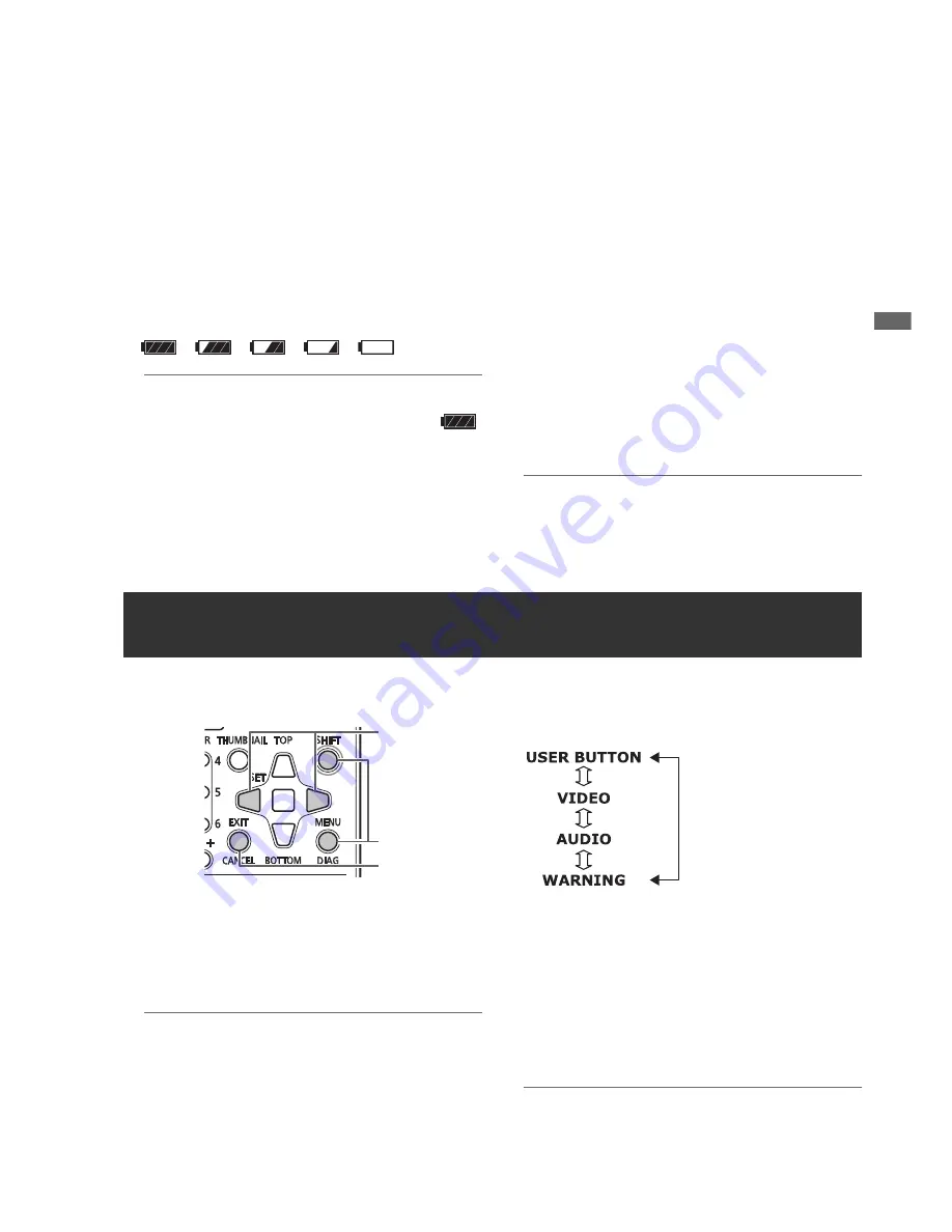
This menu shows deck information. Deck information includes
USER button, video, audio and warning information.
1
Press the DIAG button.
Indicates information on set user button values.
Once displayed, it will open the previously displayed page
when pressed next time.
◆
NOTE:
• This information is not displayed when a menu is open.
• Use the SETUP - DISPLAY - OSD OUTPUT menu setting
to switch destination of displayed output.
• Playback and other operations are not available during
DIAG display.
2
Press the Left/Right cursor buttons.
The information displayed changes with each press of the
button.
Information displayed
USER BUTTON:
Indicates the functions assigned to the USER buttons 1
- 6 and currently set values.
VIDEO:
• Format of input and output signals or absence of them
• System compression format
• Presence or absence of reference signals
and other information is displayed.
◆
NOTE:
• In 3D REC/PB and SYNC PB modes, “GENLOCK”
indicates slave side status.
Deck Information (DIAG) Icons
1,3
3
2


