background image

TROUBLESHOOTING GUIDE  

BATTERY POWER LEVEL INDICATOR FAULT CODES

TRANSAXLE DRIVE UNITS
CODE (FLASHING LED

S

)

POTENTIAL CAUSE

PROPOSED SOLUTION

One

Low voltage shut-off.  Brush motor shut down 

Recharge batteries

Check battery connections

Two

Battery charge level getting low

Recharge batteries

Three

Traction drive motor tripped

Remove overload condition and reset

Traction drive motor has short circuited

Contact a service center for testing

Four

Battery lockout has occurred

Recharge batteries right away

Eight

Controller tripped

Contact a service center for testing

Ten

High battery voltage reading

Check battery connections

None

Indicator is in sleep mode

Turn power key off then on to restore

Sequencing lights

Activation handle is engaged

Release activation bail

41

Summary of Contents for S Series

Page 1: ...ct all components to ensure that there is no concealed freight damage If such damage is discovered file a CONCEALED DAMAGE REPORT immediately with the delivering carrier The contents of this manual ar...

Page 2: ...sent WARNING Donotpickupflammableorreactivematerials WARNING Batteriesemithydrogengas Keepsparksandopenflameaway Keepbatterycompartmentopenwhencharging Performthis procedureinawellventilatedarea WARNI...

Page 3: ...edreplacementparts NOTE Allrepairsmustbeperformedbyaqualifiedserviceperson CAUTION Whenservicingthemachine donotmodifythemachinefromitsoriginaldesign NOTE Whentransportingthemachine turnthemachineoff...

Page 4: ...rger and either four 6V wet or AGM batteries The batteries must be housed in the battery compartment beneath the recovery tank To insert batteries 1 Lift the recovery water tank opening it as far as i...

Page 5: ...ndicate the amount of power left in the batteries On lead acid battery equipped units when the discharge level reaches the first red LED it is a good time to finish your scrubbing application and rech...

Page 6: ...ates charge cycle is in the second phase Green indicates charge cycle is complete On board charger 1 On board charger cord wrap 2 Quick release hook 3 These units can be equipped with an on board char...

Page 7: ...en programmed to work with the batteries that Pacific Floorcare provides Using other battery types not specified for the S Series mid size scrubber by Pacific Floorcare may impair performance of the u...

Page 8: ...if solid green the batteries are fully charged There is a red fault LED as well In the rare occurence that this LED comes on check the charger operator manual for troubleshooting guidance Charger conn...

Page 9: ...match the type of battery chosen in the original machine order Should you choose to change from the original battery type to the other the charger can be changed by re setting the dip switch To re se...

Page 10: ...oncentration and manner specified by the manufacturer for an twenty two 22 gallon solution tank The formation of excess foam could damage the vacuum motor so be sure to use only the correct amount of...

Page 11: ...p leave the faucet for that hose open the connector will act as a stop Auto off solution fill system connected to scrubber 2 Male quick connect shown on fill hose 1 2 When it is time to fill your mach...

Page 12: ...tch on the lower control panel at the rear of the machine Depress position A for 1 second and then depress position B to click off the pad drivers 4 Squeeze center lock wires inward and press center l...

Page 13: ...ushes Utilize the foot pedal to lower the scrub deck down onto the pad drivers or brushes by depressing the pedal while shifting it to the right Once clear of the lower notch lifting your foot will lo...

Page 14: ...nd high spots in the floor Proper alignment of pad To attach the pad align the front corners of the pad to the front corners of the orbital drive plate and press to attach Use the foot pedal to lower...

Page 15: ...Attach the recovery hose to the squeegee assembly neck Make sure to route the hose so that it won t interfere with the swing of the squeegee assembly Close up of squeegee assembly and blade deflectio...

Page 16: ...cally used in pools and spas to kill the bacteria in the tank that cause odors To ensure that TTS is prepared to treat your recovery tank Check the TTS bromine puck 3 Press the TTS holder and bromine...

Page 17: ...machine is powered on through a key switch on the upper control panel Turn the key to the ON position You will see the battery meter on the left side of the upper control panel light up to show the ba...

Page 18: ...t see a match use the one that most closely matches the chemical s suggested mix ratio 1 4 4 Recovery tank shown in fully open position 1 Place your 1 gallon chemical container in the holder inside th...

Page 19: ...al NOMINALWATERFLOW GPM LPM HEADSIZE TYPE LOW MED HIGH 24 inch 610 mm dual disk 1 gal 38 l 26 gal 1 l 48 gal 1 8 l 28 inch 711 mm dual disk 12 gal 45 l 3 gal 1 1 l 56 gal 2 1 l 28 x 14 inch 711 x 356...

Page 20: ...ngs The 24 inch 610 mm disk unit has settings of 50 100 140 lb 23 45 64 kg The 28 inch 711 mm 32 inch 813 mm disk scrubbers have settings of 70 110 150 lb 32 50 68 kg The 28 inch 711 mm orbital scrubb...

Page 21: ...ead is equipped with a self adjusting shroud with bristle skirt that virtually eliminates overspray and increases ease of use 3 3 To lower the squeegee lift the squeegee lever and shift it left to cle...

Page 22: ...erator heights by allowing the user to activate the trigger from any position on the handle The speed control and reverse switch are purposely located so that the operator doesn t have to let go of th...

Page 23: ...ar the notch shift it to the right and lower it into the resting position The vacuum fan will continue to run for 10 seconds in order to evacuate the recovery hose 1 2 2 Scrub deck in transport storag...

Page 24: ...stilled water if necessary X Check splash guard around scrub head for damage disk models only X Thoroughly clean entire machine X Check Bromine puck in TTS Replace if it s 25 of it s original size X V...

Page 25: ...the draining process 1 The hose is also equipped with a restriction collar that can be bent or squeezed to reduce splashing and spraying during the operation As the recovery tank drains lift the recov...

Page 26: ...n it is time for replacement or to be flipped to another edge The S Series mid size scrubber s squeegee blades have four usable edges Blade exchange is completely tool free for fast easy maintenance T...

Page 27: ...e charging is completed open the vent caps and look inside the fill wells Add distilled water until the electrolyte level is approximately 1 8 in 3 2 mm below the bottom of the fill well Clean and rep...

Page 28: ...our batteries after a full charge so your unit will most likely be in your janitor s closet or storage area but if by chance it detects low water during the cleaning operation it will only shut down t...

Page 29: ...llow proper safety precautions as indicated on your chemical product label in regards to coming in contact with solution Should the pad or brush show ample wear and have reached their replacement poin...

Page 30: ...ting the batteries as shown in the Battery connection diagram After installation is complete be sure to charge your batteries before operating the machine NOTE If changing battery types from wet lead...

Page 31: ...ront and four in the rear of the scrub head The locations of the isolators are shown below 1 2 Cross section view of FRONT of orbital scrub head with isolator locations indicated with arrows 2 Cross s...

Page 32: ...ve you access to the HEPA filter 2 Loosen the vacuum hose clamp located at the top of the HEPA filter with a 5 16 inch socket head driver and pull the cuff off of the HEPA filter 3 Inspect the HEPA Fi...

Page 33: ...istancewhenliftingthemachine NOTE Usearecommendedrampwithamaximumofa12 inclinewhenloadingorunloadinginto offtruckortrailer NOTE Whentrasportingthemachine usetiedownstrapstosecurethemachinetothetruckor...

Page 34: ...ted to the squeegee assembly Then check the upper elbow and the recovery tank orifice If debris is found clear the clog with your hands or a tool Should you have a hose available rinse the recovery ho...

Page 35: ...lty charger and it will need to be replaced However if the light is on and is blinking then the batteries aren t fully charged and the charge cycle needs to be completed Also check for the fault LED t...

Page 36: ...inline filter located on the underside of the unit be tween the wheels and the casters and clean out the debris Once clean re attach the filter and tighten it until snug Ensure the screen filter elem...

Page 37: ...ared If the clog is located here clear the clog with your hand or a tool and then drain as normal If the clog is not located at the restriction collar then it is likely in the recovery tank at the dra...

Page 38: ...most touches the casters Should it be stopping well short of this then it is likely that the recovery hose is not routed properly and has become an obstruction Properly routed recovery hose 1 To fix t...

Page 39: ...e elbow is secure on squeegee assembly neck Recovery hose or squeegee assembly may be obstructed Remove recovery hose and run water through it to check for any clogs Remove squeegee assembly and check...

Page 40: ...lit indicating the batteries need water Use the HydroLink system to fill the batteries with distilled water Vacuum motor will not turn on Squeegee is still in transport storage position Lower squeege...

Page 41: ...ies Three Traction drive motor tripped Remove overload condition and reset Traction drive motor has short circuited Contact a service center for testing Four Battery lockout has occurred Recharge batt...

Page 42: ...81 2 2 Controls Circuit breaker 30 amp 911622 2 1 1 2 Controls Switch snap with roller 911646 1 1 1 1 Controls Switch key 911647 1 1 1 1 Controls Key set of two 855012 1 1 1 1 Controls Switch push on...

Page 43: ...rews 876614 2 2 2 Recovery Filter HEPA 873304 1 1 1 1 Recovery Hose drain capped 854101 1 1 1 1 Recovery Gasket cover press in 873401 1 1 1 1 Recovery Float ball 223370 1 1 1 1 Recovery Hose vacuum 85...

Page 44: ...natex 870703 1 1 Squeegee Blade rear 40 in 1 016 mm urethane 870709 1 Squeegee Blade front 40 in 1 016 mm Linatex 870704 1 1 Squeegee Blade front 40 in 1 016 mm urethane 870710 1 Squeegee Blade rear 4...

Page 45: ...45 FRAME ASSEMBLY WITH URETHANE WHEELS...

Page 46: ...46 FRAME ASSEMBLY WITH FOAM FILLED WHEELS...

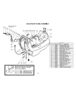
Page 47: ...47 SOLUTION TANK ASSEMBLY Head switch location for all machines built prior to March 13 2015 and before serial 102090...

Page 48: ...48 ON BOARD CHEMICAL INJECTION ASSEMBLY OPTIONAL...

Page 49: ...49 BATTERY ASSEMBLY...

Page 50: ...50 RECOVERY TANK ASSEMBLY...

Page 51: ...51 SQUEEGEE ASSEMBLY S 24...

Page 52: ...SQUEEGEE ASSEMBLY S 28 52...

Page 53: ...SQUEEGEE ASSEMBLY S 32 53...

Page 54: ...54 SQUEEGEE LINKAGE ASSEMBLY...

Page 55: ...55 HEAD LIFT ASSEMBLY...

Page 56: ...56 HEAD ASSEMBLY DRAWING 1 OF 2 S 24...

Page 57: ...57 HEAD ASSEMBLY DRAWING 2 OF 2 S 24...

Page 58: ...58 HEAD ASSEMBLY S 28 DISK...

Page 59: ...59 HEAD ASSEMBLY S 32...

Page 60: ...60 HEAD ASSEMBLY LOWER S 28 ORBITAL...

Page 61: ...61 HEAD ASSEMBLY UPPER S 28 ORBITAL...

Page 62: ...62 CONTROLS ASSEMBLY S 24...

Page 63: ...63 CONTROLS ASSEMBLY S 28 S 32 DISK...

Page 64: ...64 CONTROLS ASSEMBLY S 28 ORBITAL...

Page 65: ...65 CONTROLS ASSEMBLY BATTERYSHIELDTM CHEMICAL INJECTION SYSTEM OPTIONAL...

Page 66: ...66 ELECTRONICS ASSEMBLY S 24...

Page 67: ...67 ELECTRONICS ASSEMBLY S 28 S 32 DISK...

Page 68: ...68 ELECTRONICS ASSEMBLY S 28 ORBITAL...

Page 69: ...69 ELECTRONICS ASSEMBLY BATTERYSHIELDTM...

Page 70: ...70 CHARGER ASSEMBLY ON BOARD...

Page 71: ...WIRING DIAGRAM S 24...

Page 72: ...WIRING DIAGRAM S 28 S 32 DISK...

Page 73: ...WIRING DIAGRAM S 28 ORBITAL...

Page 74: ...WIRING DIAGRAM BATTERYSHIELD OPTIONAL 74...

Page 75: ...WIRING DIAGRAM ON BOARD CHEMICAL INJECTION SYSTEM OPTIONAL 75...

Page 76: ...for other instructions pertaining to your warranty difficulty 2 Upon compliance with the above warranty procedure all warranted repairs will be completed at no additional charge or cost to the user 3...

Reviews: