30
PERIODIC MAINTENANCE
CHANGING BATTERIES
To change the batteries in your S-Series mid-size scrubber, move the machine to an area with a level surface, turn off the power switch and
remove the key. If using an off-board charger, make sure that it is located near your machine and that your location is close to an electrical
outlet for charging after installation.
WARNING:
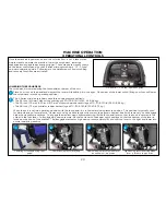
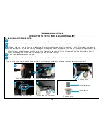
To access the battery compartment, tilt the recovery tank to the fully open position. Using proper open-ended wrench, disconnect the
main ground cable first and secure terminal away from the batteries. Disconnect main positive cable and secure terminal away from
the batteries. Loosen all terminals on the jumper cables and remove. Attach a suitable battery lifting device and lift the batteries from
the machine.
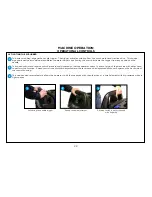
Reverse the order of the instructions above to install new batteries by orienting and connecting the batteries as shown in the Battery
connection diagram. After installation is complete, be sure to charge your batteries before operating the machine.
NOTE:
If changing battery types from wet, lead acid to AGM or vice versa, see Machine Preparation section for instructions on setting
the dip switches on your machines battery charger before beginning the charge cycle to avoid damaging or undercharging your
batteries.
Batteries are a potential environmental hazard. Consult a battery supplier for safe disposal methods.
1
2
Fully open position allowing access
to battery compartment
1
WARNING: Wear protective gloves and eye protection when handling batteries or battery cables. Avoid contact with battery acid.
WARNING: Disconnect battery connections before working on the machine.
WARNING: Short-circuiting or accidentally connecting battery posts or other metallic parts of the machine with a metal or
conductive tool can cause serious personal injury. Use proper tools and take precautions to not accidentally short circuit
battery terminals.
Battery connection diagram
2
Summary of Contents for S Series
Page 45: ...45 FRAME ASSEMBLY WITH URETHANE WHEELS...
Page 46: ...46 FRAME ASSEMBLY WITH FOAM FILLED WHEELS...
Page 48: ...48 ON BOARD CHEMICAL INJECTION ASSEMBLY OPTIONAL...
Page 49: ...49 BATTERY ASSEMBLY...
Page 50: ...50 RECOVERY TANK ASSEMBLY...
Page 51: ...51 SQUEEGEE ASSEMBLY S 24...
Page 52: ...SQUEEGEE ASSEMBLY S 28 52...
Page 53: ...SQUEEGEE ASSEMBLY S 32 53...
Page 54: ...54 SQUEEGEE LINKAGE ASSEMBLY...
Page 55: ...55 HEAD LIFT ASSEMBLY...
Page 56: ...56 HEAD ASSEMBLY DRAWING 1 OF 2 S 24...
Page 57: ...57 HEAD ASSEMBLY DRAWING 2 OF 2 S 24...
Page 58: ...58 HEAD ASSEMBLY S 28 DISK...
Page 59: ...59 HEAD ASSEMBLY S 32...
Page 60: ...60 HEAD ASSEMBLY LOWER S 28 ORBITAL...
Page 61: ...61 HEAD ASSEMBLY UPPER S 28 ORBITAL...
Page 62: ...62 CONTROLS ASSEMBLY S 24...
Page 63: ...63 CONTROLS ASSEMBLY S 28 S 32 DISK...
Page 64: ...64 CONTROLS ASSEMBLY S 28 ORBITAL...
Page 65: ...65 CONTROLS ASSEMBLY BATTERYSHIELDTM CHEMICAL INJECTION SYSTEM OPTIONAL...
Page 66: ...66 ELECTRONICS ASSEMBLY S 24...
Page 67: ...67 ELECTRONICS ASSEMBLY S 28 S 32 DISK...
Page 68: ...68 ELECTRONICS ASSEMBLY S 28 ORBITAL...
Page 69: ...69 ELECTRONICS ASSEMBLY BATTERYSHIELDTM...
Page 70: ...70 CHARGER ASSEMBLY ON BOARD...
Page 71: ...WIRING DIAGRAM S 24...
Page 72: ...WIRING DIAGRAM S 28 S 32 DISK...
Page 73: ...WIRING DIAGRAM S 28 ORBITAL...
Page 74: ...WIRING DIAGRAM BATTERYSHIELD OPTIONAL 74...
Page 75: ...WIRING DIAGRAM ON BOARD CHEMICAL INJECTION SYSTEM OPTIONAL 75...


